Introducción

Esta es una guía prerrequisito. Esta guía es parte de otro procedimiento y no debe utilizarse sola.

  1. CtSXh5SNdBfY3d4X
    • Antes de comenzar esta reparación, asegúrate de que el dispositivo esté completamente apagado.

    • Usa un destornillador Y00 para quitar los cuatro tornillos de 6.3 mm de largo que aseguran el panel trasero.

    • A lo largo de esta reparación, mantén un registro de cada tornillo y asegúrate de que vuelva exactamente a su lugar de origen.

    All my screws got stripped any ideas on how to remove?

    Almost A Mammal -

    A Y0 screwdriver seemed to work better for me.

    Tommy Morrill -

    What type of screw driver do I use to un screw the screws and which way

    Luca Capito -

  2. LoododBfWX565CM3
    LoododBfWX565CM3
    axePI5XqFET5KVdd
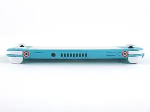
    • Usa un destornillador JIS 000 o un Phillips 000 para remover los siguientes tornillos que sujetan el panel trasero.

    • Dos tornillos de 3.6 mm en la parte superior del dispositivo.

    • Dos tornillos de 3.6 mm en la parte inferior del dispositivo.

    • Para evitar que los tornillos muy apretados se barran aplica fuerza fírmemente hacia el tornillo y gira lentamente, intenta con varios destornilladores si no sale.

  3. OdqFPXbVWUcLdDot
    OdqFPXbVWUcLdDot
    CIVhMktLorQQTIDM
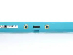
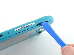
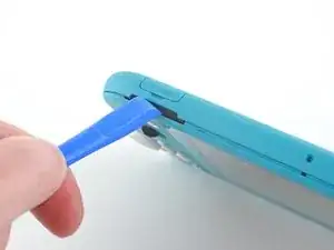
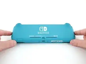
    • Inserta una herramienta de apertura en la rejilla del altavoz izquierdo en la parte inferior del dispositivo.

    • Gira la herramienta de apertura para liberar los clips que aseguran el panel trasero.

    • Evita insertar la herramienta de apertura más de lo necesario para evitar que se dañe el módulo del altavoz.

  4. wrE1q1yNyF2ogBV4
    wrE1q1yNyF2ogBV4
    Pmw5QYCTejXbIUKw
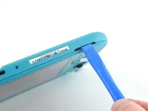
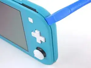
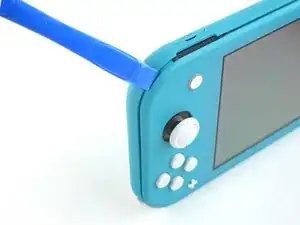
    • Desliza la herramienta de apertura por la esquina inferior izquierda para liberar los clips del lado izquierdo del dispositivo.

  5. RlPaVdXmyVJlvRdR
    RlPaVdXmyVJlvRdR
    xpNFcLWpxIZGYAZo
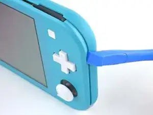
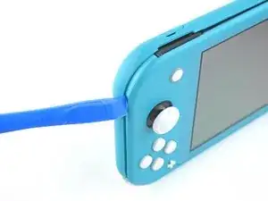
    • Inserta la herramienta de apertura en la rejilla del altavoz derecho en la parte inferior en el dispositivo.

    • Gira la herramienta de apertura para liberar los clips.

    • Evita insertar la herramienta de apertura más de lo necesario para evitar que se dañe el módulo de altavoz.

  6. nKd22DZNmOtktjJ6
    nKd22DZNmOtktjJ6
    ZFI5WyJ26AuYMJ34
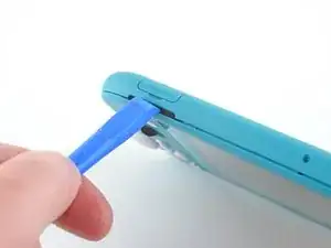
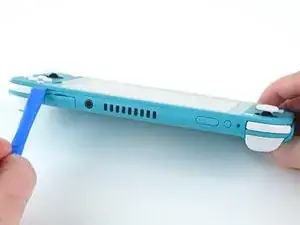
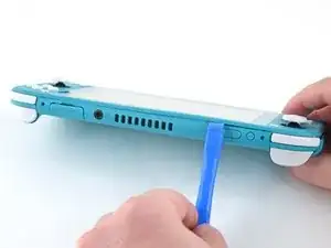
    • Desliza y empuja la herramienta de apertura por la esquina inferior derecha para liberar los clips del lado derecho del dispositivo.

  7. UB4MQPADBNC3AKGp
    UB4MQPADBNC3AKGp
    FDjmileJQ6nKxeRT
    • Continúa deslizando y apretando la herramienta de apertura a lo largo del hueco en la parte superior del dispositivo para liberar los clips.

  8. 3YVyXRJqMpDtXeYv
    3YVyXRJqMpDtXeYv
    N5JkogvdUb1o4kID
    ZH5AGwN3bXMGGKnl
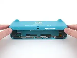
    • Levanta el borde inferior del panel trasero abriéndolo como un libro.

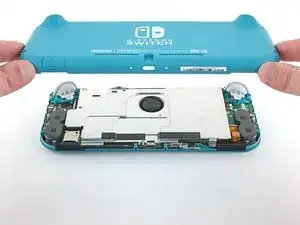
    • Remueve el panel trasero.

  9. vsR2tYTiCfHGSlh1
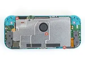
    • Usa un destornillador JIS 000 o un Phillips (de cruz) 000 para remover los cuatro tornillos siguientes:

    • Tres tornillos de 3.1 mm

    • Un tornillo de 4.5 mm

    There are four screws instead of three mentioned

    Khurram Chaudry -

    it doesnt mention 3 anywhere, and it labels all four

    Ezi -

    With how easy it seems to be to do serious damage with the next few steps, I figured I'd say that realistically you can skip steps 9-13 when doing this repair. While they provide a bit of extra security by disconnecting the battery, the left stick is completely accessible and replaceable without touching the heat shield or anything underneath (And steps 17 and 18 disconnect power from the daughter board regardless).

    Nate -

  10. FIwGjkfOhVmFCyvp
    FIwGjkfOhVmFCyvp
    LUwt2Ov3TDBmbBMy
    CxSr6WAFIqTkPknC
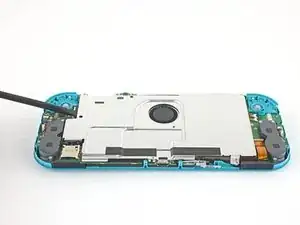
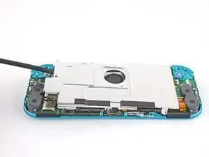
    • Usa un spudger o sus dedos para levantar la placa del escudo y sacarla del dispositivo.

    • Puede que sienta un poco de resistencia. Esto es normal, ya que la placa de escudo está ligeramente adherida al disipador de calor con pasta térmica.

    • Remueve la placa de escudo.

    • Limpia la pasta térmica vieja de la placa de protección y del disipador de calor con alcohol isopropílico y un paño de microfibra. Aplica la nueva pasta térmica al disipador de calor antes de volver a montarlo.

    You may need to replace the thermal paste on the heat sink.

    ahoz28 -

  11. NfJ4EyXkJrCSjyMP
    NfJ4EyXkJrCSjyMP
    SWRCDlfTfCNLuWJO
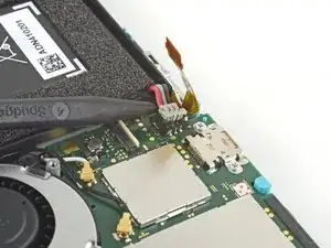
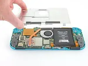
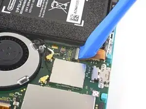
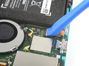
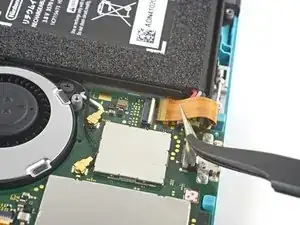
    • Utiliza una herramienta de apertura o tu uña para levantar la pequeña tapa de cierre con bisagra del conector ZIF del cable de interconexión de la placa madre.

    The clip broke off when trying to remove this cable. Audio only works through headphones and the display now won’t turn on after the clip broke. Does anyone know where I could get a clip or how I could fix it without it?

    Alexz Zepeda -

  12. EOLi3GutoqJNvstI
    EOLi3GutoqJNvstI
    hO2FmA16pHiJq2to
    • Usa un par de pinzas para sacar el cable de interconexión de su conector en la placa madre.

    I turned the unit off beforehand, I used tweezers just like the instructions said (ifixit branded) , my device sparked and now it won’t turn back on

    User Service -

    The flap came off is it important or is there a way t fix it?

    Jose Cruz R Rangel Cordero -

    We're you able to get it working without the white flap? My screen is not working after putting it back together and i noticed this white flap was falling off

    Jimmy “Ghost” Trost -

    Did you get it working without the white flap? Everything on the switch works fine except for audio going through headphones and the display not turning on.

    Alexz Zepeda -

  13. yfTkAmQeCWGhAEl2
    yfTkAmQeCWGhAEl2
    SFobIivmPhWAmdMb
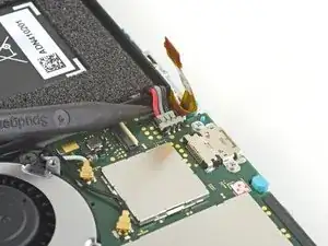
    • Usa la punta de un spudger para levantar el conector de la batería de su zócalo en la placa madre.

    Caution the connector may not be properly soldered onto the motherboard. For me it snapped off the pins and now have to find a place to get that fixed if even possible. may have bricked it.

    Craig Osman -

    Yup, broke the connector right off the motherboard. Thanks, ifixit -_-

    Justin Kerr -

    I backed out when I reached this point. I couldn't risk damaging it. Do u just need to pull it up? Did you mean that it might have been soldered shut below?

    Jannalyzer -

    You should just need to pull straight up, but make sure you’re pulling on the wires or the gray plug—do not pull on the black socket or it can snap off of the motherboard.

    Adam O'Camb -

    I pulled straight up from the south side on under 2 or three wires and held down the device as I pulled and the gray connector disconnected from the black connector on the Switch. Just be careful at this part.

    Jon -

    With how easy it seems to be to do serious damage at this point, I figured I'd say that realistically you can skip steps 9-13 when doing this repair. While they provide a bit of extra security by disconnecting the battery, the left stick is completely accessible and replaceable without touching the heat shield or anything underneath (And steps 17 and 18 disconnect power from the daughter board regardless).

    Nate -

Conclusión

Para volver a ensamblar tu dispositivo, sigue estas instrucciones en orden inverso.

Craig Lloyd

Miembro Desde 10/02/16

30254 Reputación

0 comentarios