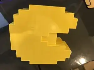
Introducción

  1. 5uPbwcLlLCbN12Zj
    5uPbwcLlLCbN12Zj
    h5iil2RfSZmqvFLe
    • Comienzo volteando el dispositivo.

  2. fUCOVjnslZhtcuWY
    fUCOVjnslZhtcuWY
    E5Iof3XInK1H4DQX
    T5EOVgnRVaAWFeqL
    • Retiro 5 tornillos de cabeza Phillips para la caja.

    • Y uno más para quitar las pilas.

  3. TEiFVQbDSTPDFKqe
    TEiFVQbDSTPDFKqe
    FYsFyZ6FoRTV4bJv
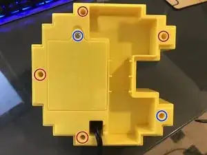
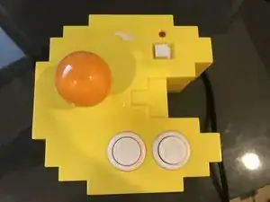
    • En el interior, todo lo que veo son gloriosos tornillos de cabeza Phillips.

    • ¡Finalmente! ¡Algo reparable!

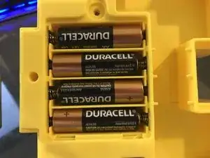
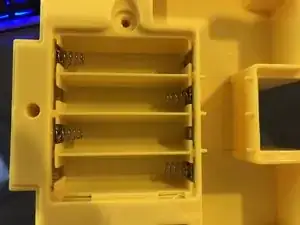
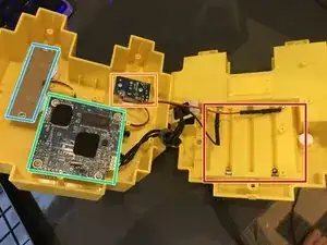
    • Compartimiento de la batería

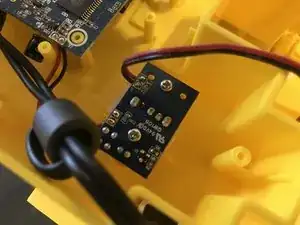
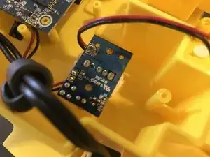
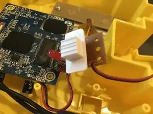
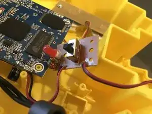
    • Interruptor de encendido y placa LED

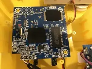
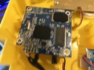
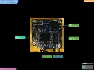
    • Placa base/placa de joystick
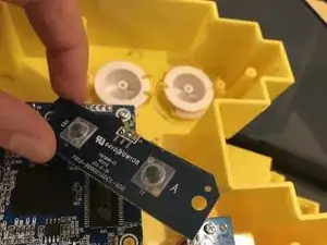
    • Botonera A y B

  4. vhaF4qC6XOu2CGct
    vhaF4qC6XOu2CGct
    KhaZmaZiUxnYgGZY
    • Empiezo con los botones.

  5. gXFRGDggm4MMFHOH
    • Ellos eran muy, muy fáciles de llegar y quitar.

  6. ctYXZXYlVICkIRIX
    ctYXZXYlVICkIRIX
    gYIAY1akMBZIMKGu
    CTePUbTE6c21umKu
    • Ahora, para la placa base.

    • 2 tornillos me meten debajo.

    • Pero, ¿qué es esto?

  7. OYacAGxe6C2Uy1cS
    OYacAGxe6C2Uy1cS
    6SSsYaRuDk5gsEHE
    JCFPXGLgriY5aJWA
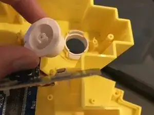
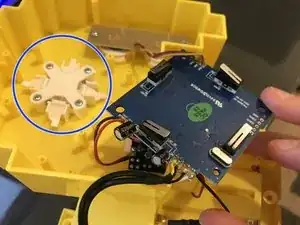
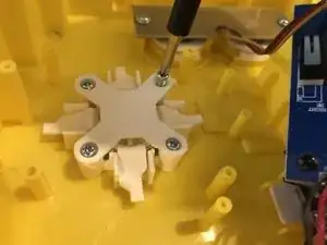
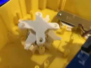
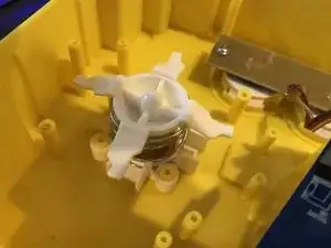
    • ¡Otros 4 tornillos y POP! está sosteniendo un resorte hacia abajo, para el joystick.

    • Sin embargo, no parecía haber una manera fácil de sacar el joystick.

  8. tOG3vMCGjugYHuw3
    tOG3vMCGjugYHuw3
    iZyhJkFQSpAOvA21
    • Finalmente, veo un regulador de potencia?

  9. xIHQJTOtdUuwUvMf
    xIHQJTOtdUuwUvMf
    oxMjBEw4CHJkUa5t
    • ¡No! Es solo el interruptor de encendido y el LED.

  10. qNHf41WbXK1nsbOn
    • Identificación de IC de PCB principal posterior:

    • Es posible que debas ampliarla para ver el texto.

  11. e2BdCaJPOE4Ld2pR
    e2BdCaJPOE4Ld2pR
    KPUs4bsCTDCirrIk
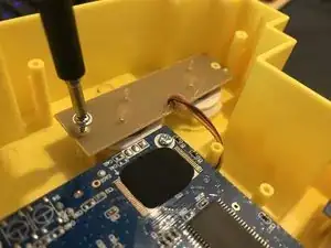
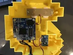
    • En conclusión, ME ENCANTA cómo es todo el tornillo J1 Phillips Head, en todo el dispositivo.

    • Es fácil meterse debajo de cada tablero.

    • Desafortunadamente, no hay enchufes, por lo que todo está soldado. Esto elimina la posibilidad de reemplazar cualquier componente eléctrico interno.

9021007

Miembro Desde 13/07/18

4358 Reputación

2 comentarios

It should not be too hard to replace stuff as long as you know how to solder. However many chips cannot be replaced as they are either epoxied on or need to be programmed before it would work in the device.

CChin -

Can you help me?

I need repair this game and need the number of part of the integrated circuit number U15 this can find at side of the red an black wire in the principal board. In my board is absolutely Imposible read it is destroyed. Only can read the first number (4) and the last (2L)

PLEASE HELP ME!!

jonatan quintero -