Introducción
Esta guía se puede utilizar como requisito previo para reparar o reemplazar piezas en el controlador Elite Series 2.
-
-
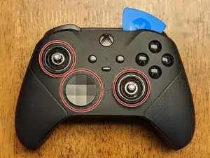
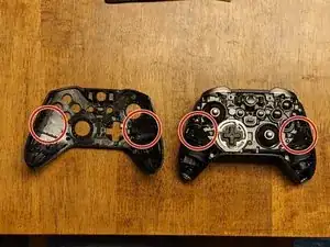
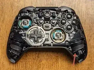
Ligeramente diferente del modelo anterior, la placa frontal debe quitarse antes que nada. Comienza quitando las tapas del joystick y la cubierta del d-pad.
-
Una vez que los elimine, deberá comenzar a trabajar con una herramienta de apertura junto con las púas alrededor de la placa frontal, comenzando en la parte superior izquierda o superior derecha.
-
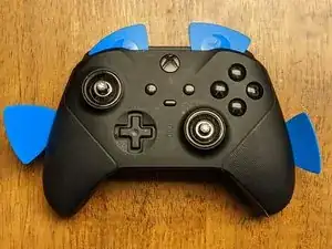
Trabaja lentamente alrededor de la placa frontal para aflojar los clips utilizando principalmente las herramientas de apertura de plástico para evitar daños a la placa frontal y los componentes internos.
-
-
-
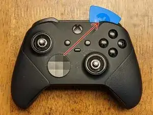
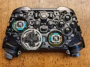
Esta es la única parte en la eliminación de la cara que sugeriría usar el spudger de metal, ya que necesitarás un poco más de palanca para liberar el adhesivo que sujeta la placa frontal.
-
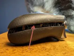
Inserta el spudger de metal en el área ubicada, pero solo hasta donde necesites hacer palanca para levantar la placa frontal. Trabaja con precaución y lentamente, ya que esto puede dañar fácilmente los componentes.
-
El adhesivo está ubicado en dos lugares y debido a que no sella el dispositivo para cumplir con los requisitos de IP-67/68, no es necesario reemplazarlo.
-
-
-
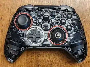
Los joysticks se atornillan en el vástago de los potenciómetros y será necesario insistir para quitarlos. Estos deberán girarse en sentido contrario a las agujas del reloj para quitarlos con cualquiera de los siguientes métodos:
-
Método 1: usar una tapa de joystick: intenta esto primero independientemente, ya que tienes menos posibilidades de dañar el dispositivo. Inserta una de las tapas de la palanca de mando en cada una de las palancas de mando e intenta girar con la mano. Si están demasiado apretados, procede con el segundo método.
-
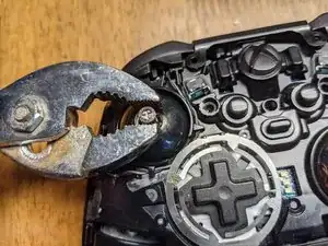
Método 2: Usar alicates: con la menor fuerza necesaria para evitar resbalones, aprieta la palanca de mando cerca de la base, donde el bisel permite un "borde plano" que las pinzas pueden sujetar. Una vez que estén sueltos, vuelve al método 1 para continuar con la eliminación.
-
-
-
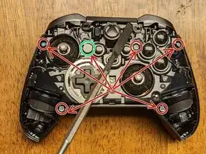
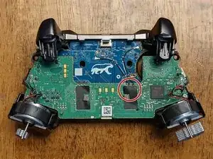
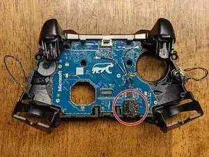
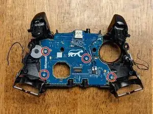
Retira los seis tornillos de seguridad T-8 que sujetan la parte delantera y trasera del controlador. Nota: uno (resaltado en verde) está cubierto por una pasta/pegatina blanca que se desmorona cuando se quita; esto te permite saber si alguien ha desarmado previamente tu dispositivo.
-
Una vez que se quitan los tornillos, puedes insertar un spudger debajo de un motor de vibración para proporcionar un poco de palanca para separar la parte frontal de la parte posterior del dispositivo.
-
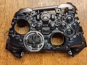
La tercera imagen muestra el conjunto frontal retirado de la cubierta posterior.
-
-
-
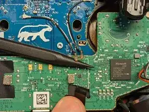
Comienza despegando la cinta (las pinzas pueden ayudar) que cubre la conexión en el tablero verde.
-
Mientras retienes la cinta, inserta el spudger de plástico con punta debajo de las conexiones, y la fuerza de empujar el spudger debajo de ellas debería ser suficiente para liberarlas de la placa.
-
-
-
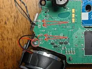
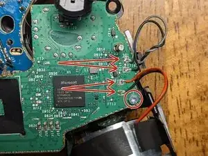
Será necesario desoldar los cables de la placa y se reemplazarán más tarde para volver a ensamblarlos.
-
Nota: cada par de hilos tiene el cable negro soldado a la conexión inferior; ten esto en cuenta para el montaje si no tienes cerca las imágenes de esta guía.
-
Nota: Es posible que pueda escaparte y no tener que desoldar estos, dependiendo de lo que necesites alcanzar (crédito para @bikemerlin), pero debido a la simplicidad y fragilidad de estas conexiones, sugeriría quitarlas para evitar daños adicionales.
-
Parte de la soldadura en este controlador requiere una temperatura muy alta para liberarse. Yo tenía el mío configurado a 450 C, sin embargo, es posible que puedas eliminarlo a una temperatura más baja.
-
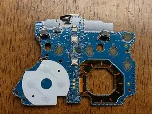
Retira los dos tornillos T-6 de la placa cerca de los motores de vibración.
-
-
-
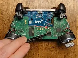
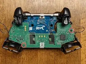
Comienza a retirar la placa base deslizándola hacia arriba a lo largo de los pines (como se indica en la imagen). Será necesario levantar el lado izquierdo de su pasador y girar el tablero en sentido contrario a las agujas del reloj en un ligero ángulo antes de que pueda deslizarse la distancia restante fuera del pasador derecho (más largo).
-
Los gatillos se flexionarán un poco, lo que deja un poco más de espacio para la placa. Como con todo lo demás en este desmontaje, ten cuidado y paciencia para evitar dañar cualquiera de los componentes.
-
Una vez que se haya retirado la placa base, es posible que ya hayas notado que el conector para auriculares se ha movido o caído. Si no lo ha hecho, retíralo del tablero ahora.
-
-
-
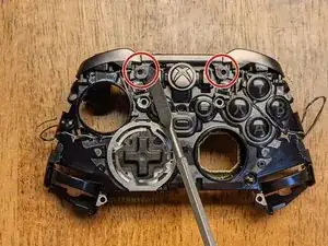
Hay dos pestañas que sujetan el retenedor de la barra en su lugar. Muévelos suavemente hacia ti con un spudger y se deslizarán hacia arriba por su propia tensión. Nota: es probable que el retenedor permanezca unido al conjunto del parachoques, pero debe retirarse del conjunto del controlador principal antes de continuar con el siguiente paso.
-
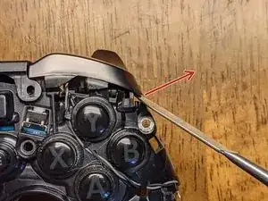
Una vez que se haya liberado el retenedor, usa nuevamente el spudger para hacer palanca suavemente en los botones hacia afuera y hacia arriba (en la dirección de la flecha en la imagen), lo que los liberará de otro clip. Haz esto en ambos lados.
-
-
-
Retira los cuatro tornillos T-6 que sujetan la placa secundaria al marco del controlador. Ten en cuenta que esta placa mantiene todos los botones restantes en su lugar, así que ten cuidado de que ninguno de ellos se pierda al quitarlo.
-
Nota: Todos los botones tienen clips que los rodean que evitan que cualquiera de los botones se instale en el lugar equivocado; asegúrate de no forzar ninguno de ellos en una ubicación diferente al volver a montar el dispositivo.
-
Al volver a montar, no fuerces nada en su lugar, ya que esto podría indicar que algo se ha instalado incorrectamente.
-
¡Eso es todo! Afortunadamente, esta guía te permitió acceder a cualquier componente que necesite ser reemplazado.
-
Para volver a armar tu dispositivo, sigue estas instrucciones en orden inverso.

8 comentarios
Hi Wayne,
thank you for the guide.
I have an issue with my controller and I can’t find the answer anywhere so here’s hoping maybe you could help me.
In shortest trigger movement setting (hair triggers) I can press LT and the movement is restricted as it should but software doesn’t registered the button as fully pressed. In Xbox Accessories I can see that the controller thinks I’ve pressed the button at around 30%.
I assume this is a hardware issue but I’m not sure which part I should be looking at. I’m a beginner tinkerer :)
Off-hand, I don't know how the controller is doing this unless it's using 3 different potentiometers per trigger. I'd be willing to bet the problem is with software though because I've had the same problem in the past, but never really looked into it. I just checked mine now and it shows the hair-triggers to be working as expected in all positions; I checked these in both the Xbox Accessories app and Windows controller settings. Instead of tearing down the controller as a first step, I'd try checking for updates with everything: Xbox Accessories, Windows, the controller firmware, and the Windows driver for the controller specifically. If any of those have an update, restart your computer (after any single update) and then re-check all of them for updates again. If that doesn't work, let me know and I can try checking into my controller components to see what all compose the trigger assembly since I need to replace a couple of buttons that are wearing out anyway!
I have tried updating firmware of the gamepad but 5.11 and beyond does not really work well on Win10 and Bluetooth (Xbox Elite 2 is recognized as standard Xbox controller and paddles don't work). However, I did verify that I encounter this issue on 4.8 (bluetooth and cable) and 5.13 (cable).
I have reverted the firmware back to 4.8. I have deleted and reinstalled Xbox peripherals drivers as well as uninstalled most Human Interface Devices drivers & restarted my PC. Didn't help.
I took screenshots hoping this would clarify my issue:
https://ibb.co/8jK5bMS - RT is in hair-trigger (shortest movement), RT is registered as fully pressed
https://ibb.co/gTcWgWG - LT is also in hair-trigger, here I'm pressing LT as hard as I can but it's registered as ~35% pressed
https://ibb.co/9wfzDMR - gamepad tester tells me that the button is not pressed fully
It'll be a few days before I can tear my controller down, but just to confirm, your right trigger is working fine and it's just the left trigger not registering the hair-trigger switch?
Yes, RT is working fine. LT works correctly in a sense that I cannot press it fully due to hair trigger lock but the press doesn’t fully register. Are there any sensors there responsible for analyzing strength of the press? The button is analog so maybe there’s something…
It’s worth adding that this has started happening after I gave the controller to 3rd party retail for LB/RB exchange. I cannot establish if they really did change the bumpers or just opened the gamepad and removed these white plastics (but I don’t see the plastics anymore).
Sorry for the late reply! Alright, I just had a chance to break down my controller again and on the back panel where the aforementioned trigger switches are, there are two daughterboards; one for each hair-trigger assembly. I'm not seeing one easily with a quick google search, but if you can find a donor to test it against, you can compare and see if that board is the problem. None of those components require soldering, but you'll need a T3 Torx to remove them. If you have a friend with the same controller, you could try asking them if you could borrow it to test the components (assuming theirs is working correctly!). Alternatively, you could try finding a "parts only" sale on eBay as a donor that might be just as cheap as buying the board, but it might be a gamble as to whether or not it will have good parts.
Regardless, as a first step, I'd just pull the controller apart and see if there is any obvious damage or loose connections; good luck!
Oh, as a side note: those white plastics aren't 100% necessary for the bumpers to function. If I were to guess, I'd say they are probably to prevent excess friction/damage to either the bumpers or switches, but as easy as they are to replace (in general), I wouldn't worry about it.
Is there anything in the guts that identifies what kind of plastic the controller is made of? Like a sticker or something molded into the inside that isn't visible in the photos? I don't see anything listed in the manual but I could have missed it.
Particularly the faceplate; I just want to pop it off to paint it, but I'm having difficulty finding information about what kind of plastic they used.
Edit: I know the center part looks like it has ABS stamped on it, but I'm not sure if the same plastic was used for the front and back pieces as well.
Crimm -
Starting center to sides from top, then center to sides from bottom worked for me.
Robert Cole -