Introducción

Prerrequisito Interno.

  1. CJyBuAcRKyHZOUfq
    CJyBuAcRKyHZOUfq
    4qMGbLH65DSyKnrI
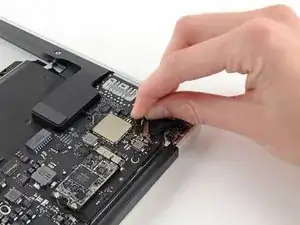
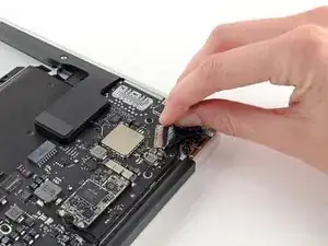
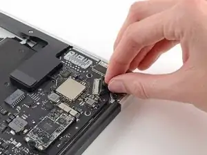
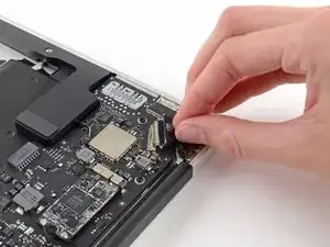
    • Agarra la lengüeta plástica asida al seguro del cable de datos de la pantalla y muévela hacia la parte superior del computador.

  2. PyH1QNR6O1xMEpN1
    PyH1QNR6O1xMEpN1
    LFxBZdcv2DWIDJ1F
    • Tira del conector de cable de datos de la pantalla directamente del socket.

    • Asegúrate de tirar del conector de forma paralela a la placa lógica, no lo levantes hacia arriba.

  3. PP6twWILoltmp3NK
    PP6twWILoltmp3NK
    XjWghlIRZmFJGBGV
    • Usa el extremo plano del spudger para extraer ambos conectores del cable de la antena hacia arriba y fuera de sus sockets de la tarjeta AirPort/Bluetooth.

    One of my terminals is broken. What solutions do you recommend me

    Omar Lopez -

    You’re actually pushing the connector from side to side toward the front of the case (or towards the track pad). It’s not a vertical motion at all.

    Jay Quilty -

    I’d also mention to be careful taking these off and putting them back on. I also accidentally pulled a terminal off it’a cable.

    Jean-Pierre Bazinet -

    If the process is taken to replace the top case, you can leave the AirPort card hanging from the antenna wires. Only remove the card’s retaining screw and slide the card to the right (direction of the antenna connectors) to separate it from the main board.

    Yishai Sered -

  4. eUcguS4kCuCpSdce
    eUcguS4kCuCpSdce
    BdoKYvDKJ2kXgTk6
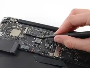
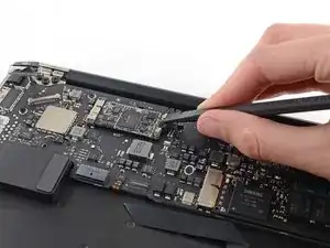
    • Desconecta el cable conector de la cámara con la punta del spudger.

    • Empuja primero de un lado del conector, luego del otro lado para "sacarlo" cuidadosamente del socket.

    • Tira del cable de la cámara paralelo a la superficie de la tarjeta I/O hacia el borde del Air para desconectarlo de su socket.

    • No levantes el cable mientras lo desconecta, puede que el socket puede romper la placa lógica.

    You’ve missed a whole section here on removing the fan. It’s still present in Step 19 pics, but gone by Step 23. It’s not that it’s difficult to work out how to do it. But, when reassembling and following the steps in reverse, it’s handy to know when to use which screws!

    Stuzzington Botulism -

    Ah! –my bad. The steps for removing Fan etc. are there –up round Step 13. It’s just your photos that are slightly out of sync, as it’s back in place again by Step 19. So, while working in reverse, it looks like it’s not been covered.

    Stuzzington Botulism -

    On getting it on — i feel it's implied by the word "push” you can walk it out with the spudger. I couldn't wanage that, and instead walked it out by taking the cord between my index and thumb and walking it out by pulling it to the right and then the left repeatedly in a

    Elijah Kennedy -

  5. P1sNLeqNFBr5Jnwf
    P1sNLeqNFBr5Jnwf
    5exa3msIehcDwPRC
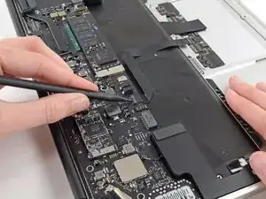
    • Usa la punta de un spudger o su uña para levantar la solapa de retención del socket ZIF del cable plano del trackpad.

    • Asegúrate de que está levantando la aleta de retención con bisagras, no el socket en sí.

    • Tira el cable plano del trackpad hacia afuera del socket hacia el borde delantero del Air.

  6. gUYJySRPRrkO5wt3
    gUYJySRPRrkO5wt3
    5EuM2gVmUDKR2vjX
    FRDlWmxCmcp5xuoc
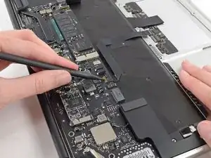
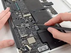
    • Usa la punta del spudger para abrir la solapa de retención del socket ZIF del cable plano del teclado retroiluminado.

    • Asegúrate de que está levantando la aleta de retención con bisagras, no el socket en sí.

    • Usa el spudger para gentilmente retirar el cable plano del teclado retroiluminado fuera del socket.

    Do you know where i can buy the retaining clip ?

    Jo (MemePasGame) -

    Not sure you can. I’d just use some kapton tape to hold it in place and call it good.

    maccentric -

  7. AlOVWWKGZcLhsaeN
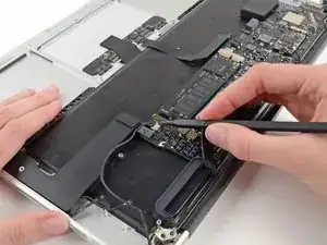
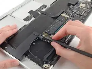
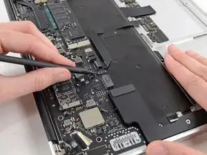
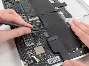
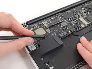
    • Usa la parte plana del spudger para levantar el cable conector del parlante derecho fuera del socket de la placa lógica.

    • Es recomendable levantar por debajo de los cables.

    What is this cables for?

    great.ryankim -

    It’s a speaker cable

    maccentric -

    This is the one that gave me the hardest time!!! It does pop up and out tho.

    Edward Mills -

  8. qvLbZjBps2dASxRN
    • Remuevw los seis tornillos 6.3 mm T5 Torx que sujetan la placa lógica a la carcasa superior.

    • En algunos modelos puede que los tornillos sean 4.1 mm T5 Torx.

    When re-assembling the motherboard, attach all 6 screws but do not completely tighten yet.

    First make sure the rubber gasket is sitting properly, that the 7th screw hole (from Step 18) is properly aligned, and the Airport wire is sitting properly and also not caught under the heat sink.

    Once everything is well aligned, start tightening the screws while watching out for the alignment. I found it useful to keep an eye on screw-hole from Step 18 as a reference.

    Rany -

    Going in this order, there is a 7th screw securing the logic board to the frame; the heatsink is secured to the logic board with 4 screws, and secured to the frame with 1 more screw. Either take the heatsink off first, or remove that last screw underneath two small black wires, next to the left (as viewed when using the computer; if the computer is flipped over with the cover off and the monitor hinge end of the computer farthest from you, it is in the far right corner) set of three big torx screws that hold the hinge in place. The exact location of this screw is pictured in step 35's second picture; the screw goes through the loop visible below the rubber fan insulator. Scoot those 2 li'l wires out of the way and remove that screw, then the logic board comes right out. If this isn't clear, please let me know and I'll try to describe it better, or add a photo. If I'm posting this to the wrong instruction page, let me know; I was pretty sure I correctly identified my rig, but if not, sorry for the N00bage.

    Fox MacLeod -

    I got an extra screw hiding under the rubber gasket holding the end of the heatsink to the chassis. Ended up bending the heatsink a little cause I wasn't looking for it.

    Corvallis Computer -

    In the model I was working on, the 6th screw (in the middle) was hiding under the Samsung RAM module. Simply remove the one T5 screw holding it in, slide the RAM module out, and the 6th screw will be exposed.

    Tim -

    “Samsung RAM module”… do you mean the SSD? That stick of NVRAM is totally your hard drive.

    FeRD -

    Exactly, he means SSD (storage) the RAM (memory) is soldered to this 820-00165 logic board. Also on this model the 2015 MBA there is no logic board retaining screw under the SSD

    Peter Newman -

  9. mYEeRWC1rrTU2GRe
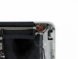
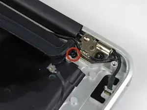
    • Remueve los dos tornillos interiores 4.9 mm T8 Torx que sujetan el retenedor del cable de la antena y la bisagra embrague izquierda a la parte superior de la carcasa.

    This is the same screws as step 17.

    Joseph Lee -

    In both the online and the PDF version, Steps 17-18 and Steps 29-30 are identical. At which stage should you actually remove the display screws?

    adlerpe -

    Good catch! We did some sleuthing and it looks like a couple guides did indeed have an extra section of steps! All better now =)

    Sam Goldheart -

    In my computer these screws were the same size as the other side’s hinge screws. All 6 are the same size.

    Yishai Sered -

  10. Zv1bjAsOBE3OAMpZ
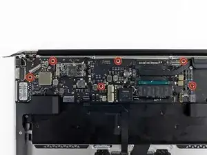
    • Empuja el retenedor del cable de la antena un poco y remueva los tornillos 3 mm T5 Torx que sujetan el disipador de calor de la parte superior de la carcasa.

    This step is not needed

    mayer -

    It’s not clear what you mean by “This step is not needed.” If you want to remove the logic board from the upper case in order to put it onto your replacement upper case, you will have to remove this screw.

    Richard Garella -

    This step is only needed if you’re replacing the ENTIRE top case. Simply swapping out the trackpad unit does not make this step necessary. This entire tutorial assumes you’re replacing the entire top case which is an expensive mistake if you’re simply replacing the trackpad and/or keyboard. The keyboard is removable as well despite those many tiny rivets. Save money and time by not replacing the entire top case for a bad trackpad and/or keyboard. I needed to accomplish this step because I also removed and replaced the keyboard.

    airshack -

    NOTE: There is a sort of clamp/washer attached to this screw that I didn’t know about until I flipped the laptop up on its side and it fell onto the desk. Also: you need to reset it *before* the motherboard

    Edward Mills -

    In my computer this screw was not there, nor was a related washer. I got it used so perhaps someone has already been there and did not replace the screw.

    Also, the photo here shows how this end of the fan gasket is placed

    .

    Yishai Sered -

  11. rMGCB2mYHkJbvyyM
    rMGCB2mYHkJbvyyM
    XWUPBZZWaDOxlPQW
    rcxEOjUVUDeWAv1H
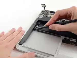
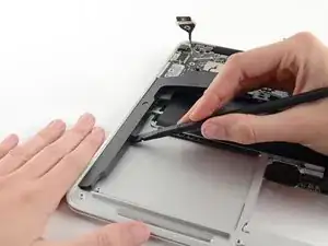
    • Desliza la parte plana del spudger por debajo del parlante derecho desde la parte más cercana a la bisagra hasta el borde frontal del Air para soltar el adhesivo.

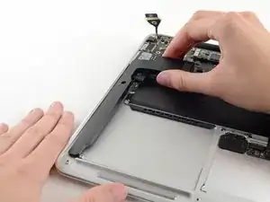
    • Remueve el parlante derecho de la carcasa superior.

    You don’t really *have* to remove the speaker, especially if your replacement upper case assembly already includes the speakers.

    Alexander Zub -

    I found the same. If you already have speakers in your new upper case, you can leave them. When you put the logic board back in, it will be a tight fit. I had to start with the corner near the right hinge (the Thunderbolt port corner) and work it in to place.

    Richard Garella -

    If your keyboard and/or trackpad need replacing you do not have to replace the entire top case.

    airshack -

  12. ahuuUdNuWAdNm1ZN
    ahuuUdNuWAdNm1ZN
    X1ufJPVJVHZtlKHO
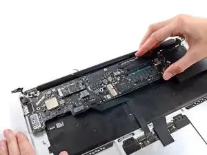
    • Cuidadosamente remueve la placa lógica de la carcasa superior, teniendo en cuenta cualquier cable que pueda quedar atrapado.

    • Durante el armado:

    • Mantén los cables sueltos alejados de la placa así no quedaran atrapados debajo de esta.

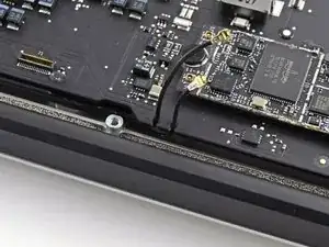
    • Asegúrate que los cables de la antena estén en sus respectivas muescas, como se resalta en la segunda imagen.

    It’s probably worth mentioning here that during reassembly you want to tuck the rubber gasket under the extension of the heat sink that the fan slots into.

    David Bonner -

Conclusión

Para reensamblar tu dispositivo, sigue estas instrucciones en orden inverso

Walter Galan

685928 Reputación

0 comentarios