Introducción
Usa esta guía para completar el reemplazo de tu placa lógica
-
-
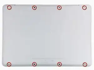
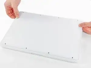
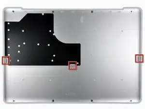
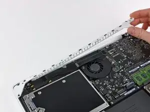
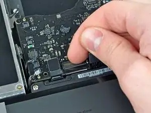
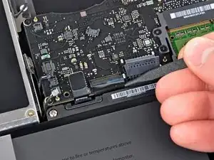
Levante ligeramente la tapa inferior cerca de la abertura de ventilación.
-
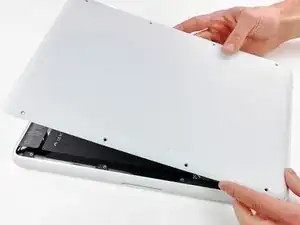
Continúa pasando los dedos entre la parte superior e inferior hasta que salgan los clips de retención.
-
-
-
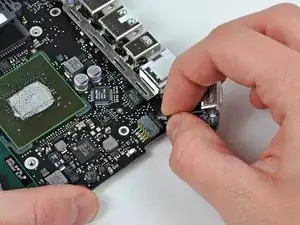
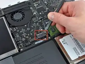
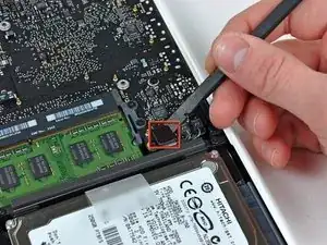
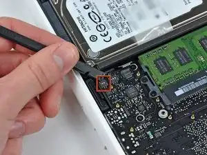
Usar la punta plana de una spudger para levantar el conector de la batería de su enchufe en la placa lógica.
-
-
-
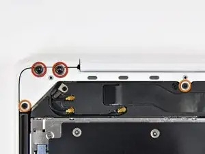
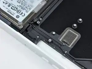
Remueve los siguientes tornillos del lado del disco óptico de la rejilla trasera:
-
Dos Torx T8 de 10mm
-
Dos Phillips de 5.2mm
-
-
-
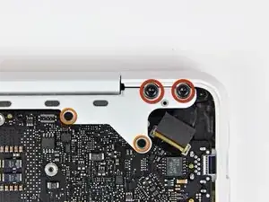
Remueve los siguientes tornillos del lado de los puertos de la rejilla trasera:
-
Dos Torx T8 de 10mm
-
Dos Phillips de 5.2mm
-
-
-
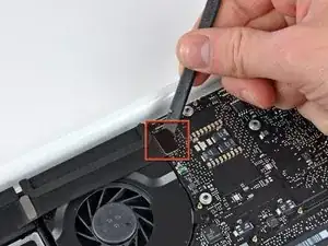
Usa el lado plano de un spudger para levantar el cable plano del Airport/Bluetooth de la placa lógica.
-
-
-
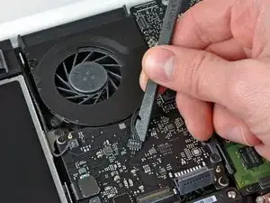
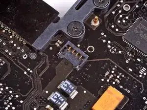
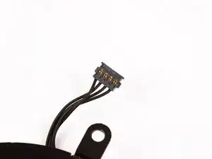
Usa un spudger para levantar el conector del ventilador hacia arriba y fuera de su zocalo en la placa lógica.
-
-
-
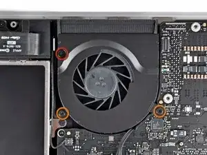
Remueve los siguientes tres tornillos asegurando el ventilador a la carcasa superior:
-
Un tornillo Phillips de 7.1 mm.
-
Dos tornillos Phillips de 5 mm.
-
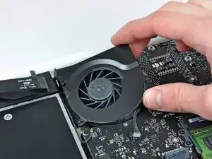
Levanta el ventilador afuera de la carcasa superior.
-
-
-
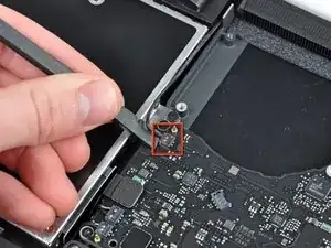
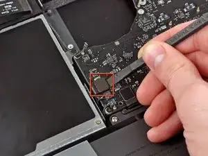
Cuidadosamente levanta el conector delicado de la bocina trasera de la placa lógica. Estos pequeños conectores de bocinas L/R son muy fáciles de romper.
-
-
-
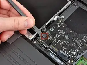
Usa el lado plano de un spudger para levantar el conector del lector óptico hacia arriba de la placa lógica.
-
-
-
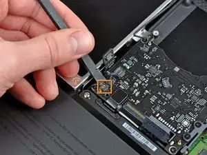
Usa un spudger para levantar el conector conector de la bocina derecha y el LED de reposo hacia arriba de la placa lógica.
-
-
-
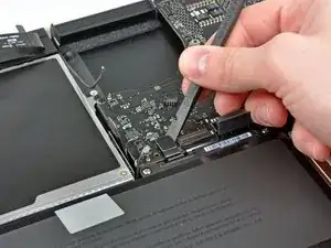
Usa el lado plano de un spudger para levantar el conector del cable plano del TouchPad de la placa lógica.
-
-
-
Usa tu uña para levantar la solapa de bloqueo en el zocalo ZIF del cable plano del teclado.
-
Usa la punta de un spudger para deslizar el cable plano de un teclado afuera de su zocalo.
-
-
-
Usa el lado plano de un spudger para levantar el conector del cable del disco duro hacia arriba de la placa lógica.
-
-
-
Usa un spudger para levantar el conector de la bocina izquierda y del micrófono hacia arriba de la placa lógica.
-
-
-
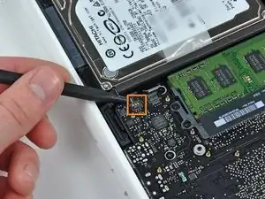
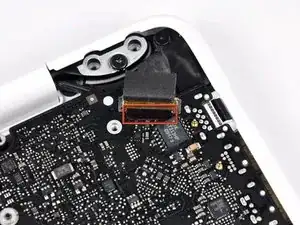
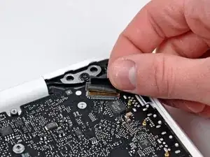
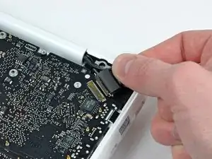
Agarra la lengüeta de plástico asegurada al seguro del cable de datos de la pantalla y rótalo hacia el lado de DC-In de la computadora.
-
-
-
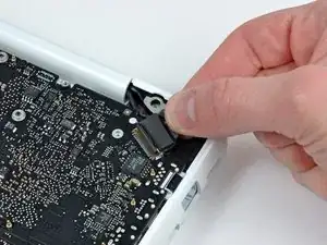
Tira gentilmente del conector del cable de datos de la pantalla lejos de su zocalo en la placa lógica.
-
-
-
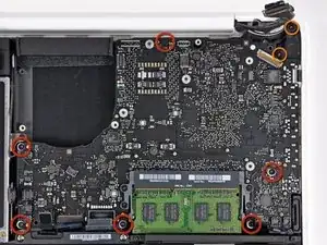
Remueve los seis tornillos Torx T6 de 4.1 a 4.4 mm asegurando la placa lógica a la carcasa superior.
-
Remueve los dos tornillos Torx T6 de 4.1 a 4.4 mm asegurando la placa MagSafe a la carcasa posterior.
-
En algunos modelos, estos tornillos pueden ser un T7. Se cuidadoso de no rodarlos con una punta más pequeña.
-
-
-
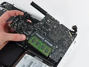
Levanta el lado de la placa lógica opuesto a los puertos para sacarla de la carcasa superior.
-
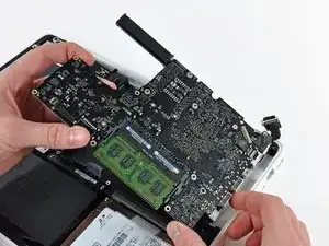
Rota la placa lógica lejos de la carcasa superior hasta que los puertos salgan del borde moldeado en la carcasa superior.
-
Tira de la placa lógica y placa MagSafe lejos del borde de la carcasa superior como una pieza.
-
-
-
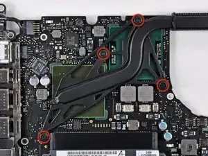
Remueve los cuatro tornillos Phillips con reborde de 8.3 mm asegurando el disipador a la placa lógica.
-
-
-
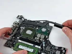
Con cuidado voltee la placa lógica al revés
-
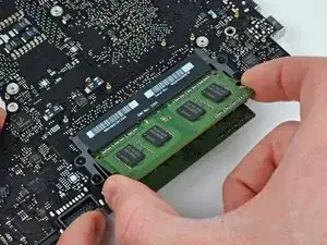
Suelte las pestañas en cada lado del chip, empujando simultáneamente cada pestaña hacia afuera.
-
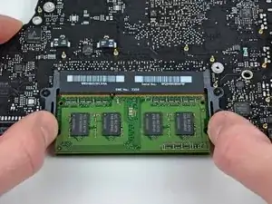
Para volver a armar tu dispositivo, sigue estas instrucciones en orden contrario

11 comentarios
Starting in Step 10 there are very delicate connectors that are easily broken. I first attempted to lift one with a spudger and noticed it begin to crack. I found an alternative way that worked perfectly for all of these types of connectors. Using 2 straight pins, press the point of each one just on either side of the connector, between the connector and the housing. Then use each pin to evenly pry the connector up. It will pop right out of the socket with no damage.
My macbook has been gradually getting hotter and running slower. Recently it started displaying some weird behavior that I assumed was a failing HD since it's 5 years old. I ran the extended Apple Hardware Test (more than once for confirmation) and got the following error: 4SNS/1/40000000: TN1D-104.000. Googling suggested that the CPU's northbridge was reaching a temperature of 104 deg. C and that macbooks have issues with overheating that can be attributed to poor application of thermal paste.
I followed this guide. The fan, heatsink fins and the underside of the logic board were almost completely clogged with dirt and cat hair. Got rid of it that, cleaned the excessive globs of dried up thermal paste, reapplied thermal paste and put everything back together. The macbook is now running cooler and faster and video is running quite smoothly which was an issue previously. I reran the Apple Hardware Test which reported, "No trouble found".
aeevr -
Hi, I have a mac book 4.1 with a gma x3100 32bit graphic chip, white plastic enclosure just like the one in the pictures.
The tutorial seems pretty detailed, great job, I feel confident I can get through without problems but I have a couple of questions.
Which logic board model will suit my mac book best, I also read that the heat sink and the SuperDrive connectors may be different, is that true?
thanks!
Andrea.
Andrea -
This page is for a macbook 6.1 or 7.1. Wrong page for your mac!
rozakis -
According to this page http://support.apple.com/kb/HT1651?viewl..., the 8 screws are not identical.
Can anybody tell me where each kind of screw is supposed to go?
Gregoire -
They are all 100% Identical. You were probably looking at a different model, or Apple has entered the wrong information... Hey, It happens...
weeowey weeowey -
The screws on the Late 2009 are identical. The blue lock compound might make tightening some require a little more effort.
svenaustx -
Can I replace it with a SATA 3 cable?
nm -
A1342 macbook does not have the right controller to support sata III
weeowey weeowey -
hi, i just got back from the apple store and they are really keen for me to upgrade to a new laptop since my battery is old and the screen is cracked, so glad i found ifixit i would love to upgrade this puppy! gonna make it a real sleeper! styler hall wrote about sticking 16 gb of ram in his a 1342 ? is this a simply mather of ordering 3 4gb sticks ?aslo i currently have 4 gb and would like to upgrade to 8 ( or indeed 16) does that mean i need to buy all new sticks or can i continue to use the old one and stick a new one next to it ?
thanks again mick van aar, perth western aus.
michelvanaar -
The A1342 will take up to 16 GB of RAM, however, there are only two RAM slots, so use two 8-GB RAM modules. Other World Computing (OWC) is a great reference source for info on exactly which RAM to use with which model; prices are usually much better on EBay though. Add an SSD from OWC and your machine will really scream!
I hope that helps!
gdesbrisay -
Gregoire is right. The 8 screws are absolutely NOT identical, I’m looking at them right now, weeowey weeowey.
John Guzman -
I just wanted to say that, in 2020, i used these instructions to replace the magsafe socket on my A1286, mid-2012, pre-Retina MacBook Pro. The internal layout is not quite the same but close enough for me to do the job. I skipped the steps of fully disconnecting the fans and speakers because of what others had said about breaking the sockets. it just meant I had to be extremely careful when lifting up the main board so that I did not tear and break the connections. I was able to disconnect the old magsafe socket with the board flat and in situ, but there was no where near enough room to be able to aline and press home the new par home. Reluctantly i had to lever up the board. This was difficult as there is a tapped post that holds a screw in the way close to where the USB sockets are, that prevented the board lifting up and out. I had to be quite forceful to manouevre the sockets out from the edge of the case.
Paul Burridge -