Introducción
Esta guía te guiará para que puedas reemplazar los módulos de joystick en tu Nintendo Switch Pro Controller. Esta guía de reemplazo requerirá que desueldes y sueldes tus joysticks de reemplazo de vuelta a la placa de circuito. Si necesitas aprender a soldar, consulta esta guía.
-
-
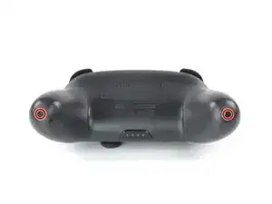
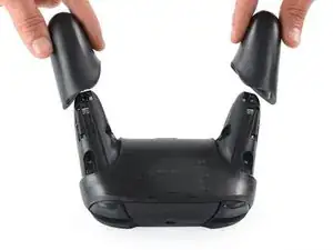
Voltea el mando para que las pegatinas de los modelos estén orientadas hacia el techo.
-
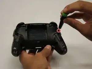
Usa un destornillador JIS #00 para quitar los dos tornillos negros de 8,4 mm que sujetan las manijas, ubicados en los extremos de las manijas.
-
-
-
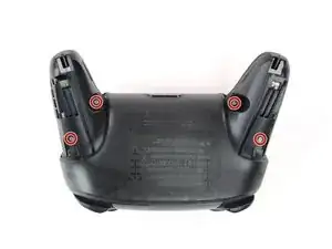
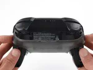
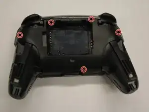
Utiliza un destornillador JIS n.º 00 para quitar los cuatro tornillos plateados de 6,8 mm que sujetan la cubierta de plástico transparente posterior.
-
-
-
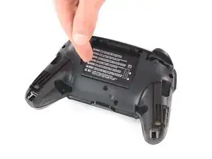
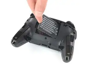
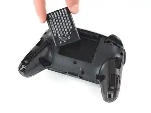
Retira la batería de iones de litio haciendo palanca con una uña o una herramienta de apertura de plástico en el lado izquierdo.
-
-
-
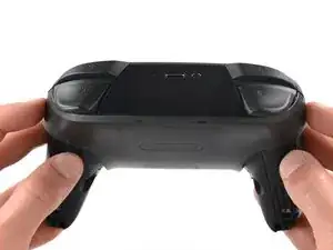
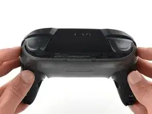
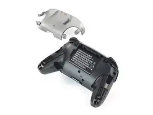
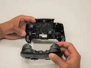
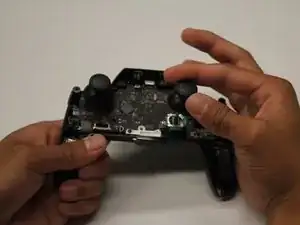
Saca con cuidado la placa frontal del cuerpo usando una herramienta de apertura de plástico.
-
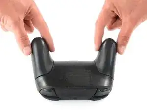
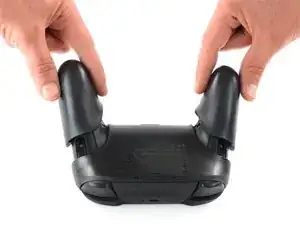
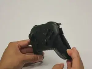
Separa las cubiertas de plástico separándolas del cuerpo del controlador.
-
-
-
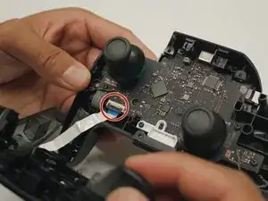
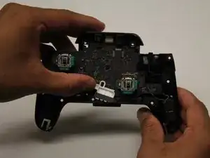
Utiliza una herramienta de apertura de iFixit para subir la pestaña de bloqueo del conector ZIF.
-
Retira con cuidado el cable plano del conector.
-
-
-
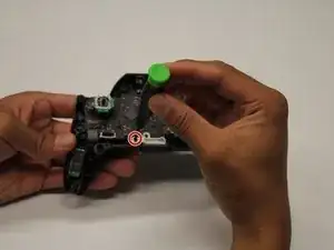
Retira el tornillo de cabeza redonda de 5 mm con un destornillador Phillips #00.
-
Usa tu uña para alejar la luz LED de su ranura.
-
-
-
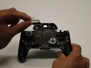
Quita los tres tornillos negros de cabeza redonda de 5 mm con el destornillador Phillips #00.
-
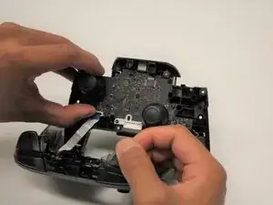
Afloja la placa de circuito del chasis tirando suavemente de la esquina inferior derecha.
-
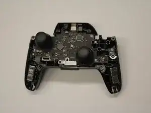
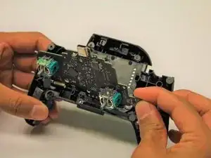
Levanta la placa de circuito para exponer su parte trasera.
-
-
-
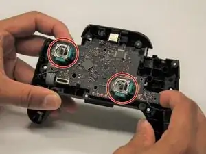
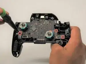
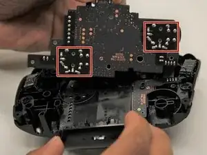
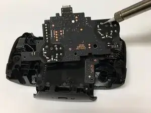
Gira hacia la parte trasera del circuito para tener acceso a las soldaduras.
-
Desoldar todas las uniones soldadas delineadas.
-
Retira el módulo de la palanca de mando de la placa de circuito.
-


Para volver a ensamblar tu dispositivo, sigue estas instrucciones en orden inverso.

19 comentarios
I managed to replace mine with much difficulty with the soldering but the stick does not seem to turn fully anymore, both with the replacement and the original. For reference, when I go to test it, it no longer registers as reaching the outer circle when pressed all the way down. Similarly when I go to calibrate it, it only reaches up til about the 2nd outer circle, not enough to actually trigger the green arrow. Since this seems to occur on both the replacement and original stick now, I’m guessing this must be some issue that arose while I was struggling with the desoldering process. Anybody have any ideas what might be causing my issue? Have I just damaged it beyond repair?
Tyler -
Without pictures it is impossible to tell, but there is the possibility that you strips the metal connection on the solder point. This is fixable by “bridging” the connection. You will want to find schematics of the wiring for the PCB and then solder the wire over to the next connection.
As a side note, I should mention that I have never tried this on a controller of any sort and that I have only used this method on keyboards with single wire connections. It is possible that the connection in a controller PCB have more going on and that this technique will not work.
Gavin A -
I have the same problem, I buy 2 joystick module from iFixit and the two gave me the same issue, the joystick module don't reach the green arrow.
I can't calibrate because of that issue.
Any ideas?
I have also had the same issue with replacement, only reaches roughly 75%. I contacted ifixit and they sent me a replacement thinking it might be a faulty pot, I installed the new stick and have the same issue. Maybe different years used different resistance.
See my answer a bit down. I think it has to do with the resistance of the module. I had the same issue with the part I received from iFixit, the original part has a resistance of 1150 ohm, but the replacement is 1600 ohm. And I have a different module which is about 500 ohm, and that works just fine.
Excellent guide. Thank you. Saved me from having to buy a $70 controller.
One comment though, all the screws are actually Phillips #0 except for the grip screws, which are Phillips #00
Brian -
I managed to repair a drifting stick input without any soldering by just replacing the potentiometer in the stick module. You can pry open the housing on the sides, swap it out (make sure it’s the right orientation), and snap it back into place. Potentiometers for Dualshock 4 analog sticks worked for me—apparently these parts are industry standard. Doing this from now on for all my drifty sticks.
Hi Scott —
.
So, first off, thanks for the tip! Now, I realize I may be asking a bit much of you here, but, is there any chance you could post/take/fwd any pics of the (sub)procedure you describe? It’d be really helpful to have a reference like that before I tear into a functioning joystick — even if it has a sporadic (though no less infuriating for that) issue.
.
If that’s not feasible, then perhaps you know of and can post a link to a decent guide for doing so on any of the platforms that use these (apparently standard) items?
.
Thanks in advance for any help on this! :oD
anatinus -
I would like to try it your way. Do you have any pictures or something like it. Maybe a video?
Be carefull, these screws are super easy to strip even with the right tools.
Lukas Eberharter -
I tried editing these instructions after I had trouble with stripping screws, but it doesn't seem to take. The issue is that these are JIS and not Phillips screws. They are VERY similar looking but a Phillips head screwdriver will strip the screws.
Isaac Webb -
I tried using a Philips #00 screwdriver but it didn’t work
vincent ingrassia -