Introducción
¡Esta es una guía de requisitos previos solamente! Esta guía es parte de otro procedimiento y no debe usarse sola.
-
-
Usa un destornillador Y00 para quitar los cuatro tornillos de 6.3 mm de largo que aseguran el panel trasero.
-
-
-
Usa un destornillador JIS 000 o un Phillips 000 para remover los siguientes tornillos que sujetan el panel trasero.
-
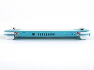
Dos tornillos de 3.6 mm en la parte superior del dispositivo.
-
Dos tornillos de 3.6 mm en la parte inferior del dispositivo.
-
-
-
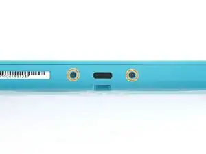
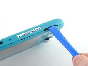
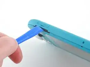
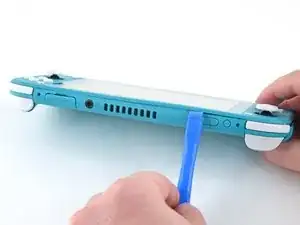
Inserta una herramienta de apertura en la rejilla del altavoz izquierdo en la parte inferior del dispositivo.
-
Gira la herramienta de apertura para liberar los clips que aseguran el panel trasero.
-
-
-
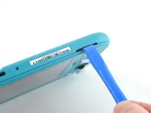
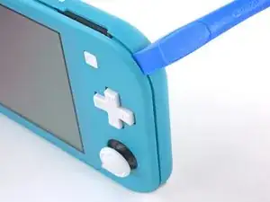
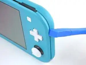
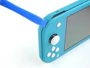
Desliza la herramienta de apertura por la esquina inferior izquierda para liberar los clips del lado izquierdo del dispositivo.
-
-
-
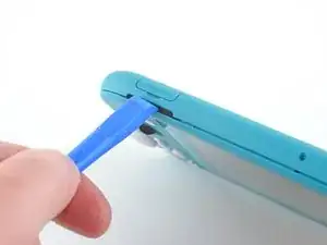
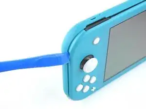
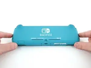
Inserta la herramienta de apertura en la rejilla del altavoz derecho en la parte inferior en el dispositivo.
-
Gira la herramienta de apertura para liberar los clips.
-
-
-
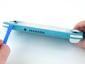
Desliza y empuja la herramienta de apertura por la esquina inferior derecha para liberar los clips del lado derecho del dispositivo.
-
-
-
Continúa deslizando y apretando la herramienta de apertura a lo largo del hueco en la parte superior del dispositivo para liberar los clips.
-
-
-
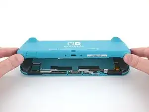
Levanta el borde inferior del panel trasero abriéndolo como un libro.
-
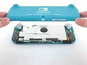
Remueve el panel trasero.
-
-
-
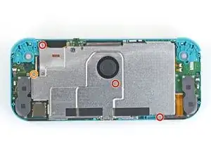
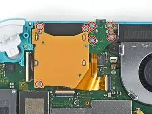
Usa un destornillador JIS 000 o un Phillips (de cruz) 000 para remover los cuatro tornillos siguientes:
-
Tres tornillos de 3.1 mm
-
Un tornillo de 4.5 mm
-
-
-
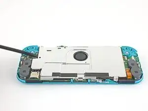
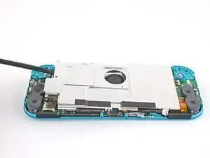
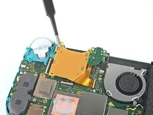
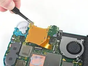
Usa un spudger o sus dedos para levantar la placa del escudo y sacarla del dispositivo.
-
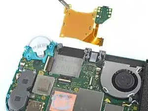
Remueve la placa de escudo.
-
-
-
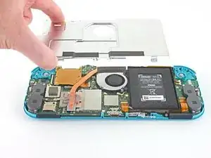
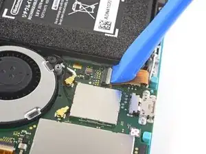
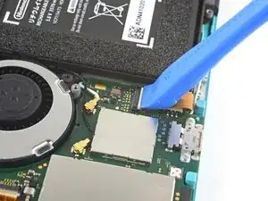
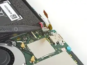
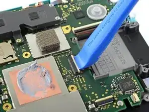
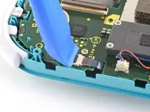
Utiliza una herramienta de apertura o tu uña para levantar la pequeña tapa de cierre con bisagra del conector ZIF del cable de interconexión de la placa madre.
-
-
-
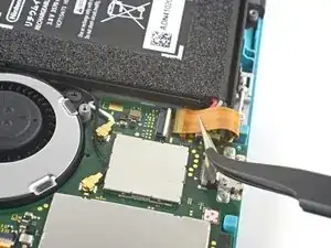
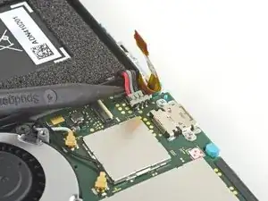
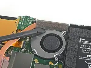
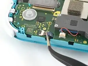
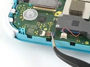
Usa la punta de un spudger para levantar el conector de la batería de su zócalo en la placa madre.
-
-
-
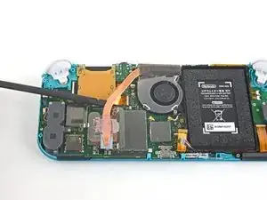
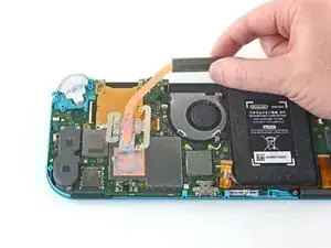
Usa el extremo plano de un spudger o tus dedos para despegar con cuidado la espuma que está adherida al ventilador.
-
-
-
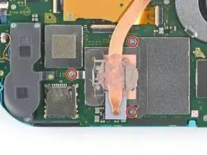
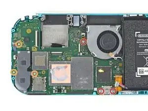
Usa un destornillador JIS o un destornillador oficial iFixit PH 000 para quitar los tres tornillos de 3 mm que aseguran el disipador de calor a la placa madre.
-
-
-
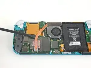
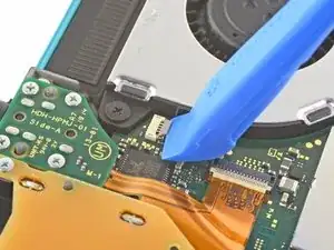
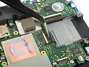
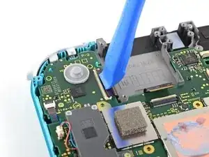
Utiliza una herramienta de apertura o tu uña para levantar la pequeña tapa de cierre con bisagras del conector ZIF del cable del lector de tarjetas de juego.
-
-
-
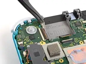
Utiliza un destornillador JIS 000 o un destornillador oficial iFixit PH 000 para retirar los siete tornillos de 3,1 mm que sujetan el lector de tarjetas de juego y la toma de auriculares.
-
-
-
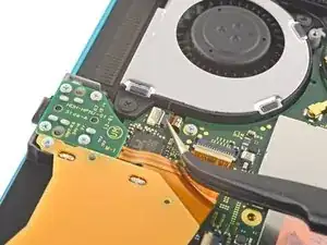
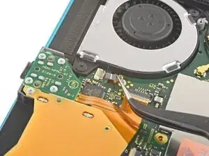
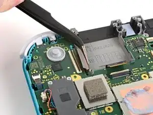
Utiliza unas pinzas o tus dedos para levantar con cuidado el lector de tarjetas de juego y maniobrar hacia la izquierda para sacar el cable de su conector.
-
Retira el lector de tarjetas de juego y la toma de los auriculares.
-
-
-
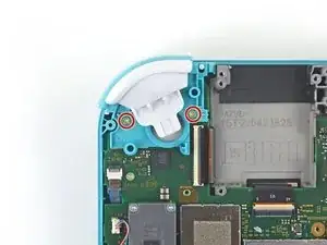
Utiliza un destornillador JIS 000 o un destornillador iFixit PH 000 oficial para quitar los dos tornillos de 4,5 mm que sujetan el conjunto del botón disparador derecho a la placa base.
-
-
-
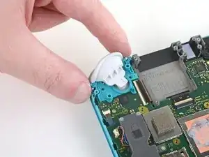
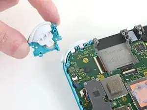
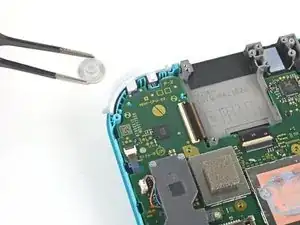
Usa un par de pinzas o tus dedos para quitar la almohadilla de goma del conjunto del botón del gatillo derecho si no quedó adherido al conjunto del botón.
-
-
-
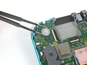
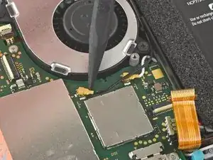
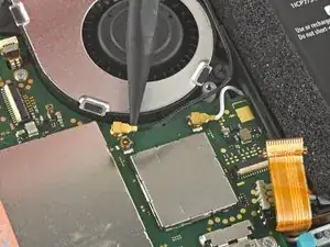
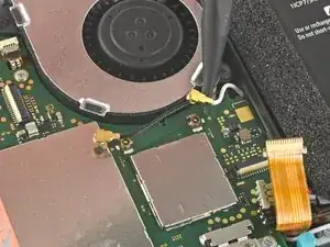
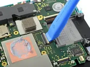
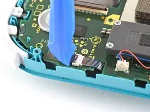
Usa la punta de un spudger para sacar el cable negro de la antena de su zócalo en la placa base.
-
Repite el mismo proceso para el cable de antena blanco.
-
-
-
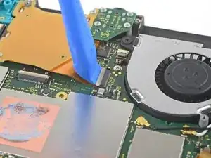
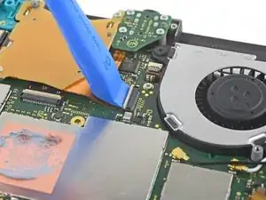
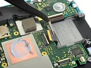
Usa una herramienta de apertura o la uña para levantar la pequeña solapa de bloqueo con bisagras en el conector ZIF del cable del ventilador.
-
-
-
Usa una herramienta de apertura o tu uña para levantar la pequeña solapa de bloqueo con bisagras en el conector ZIF del cable de pantalla.
-
-
-
Usa un par de pinzas para deslizar el cable de la pantalla fuera de su conector en la placa base.
-
-
-
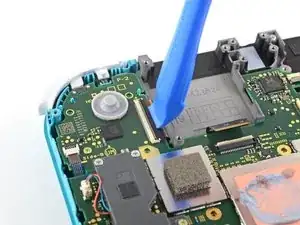
Utiliza una herramienta de apertura o la uña para levantar la pequeña solapa de bloqueo con bisagras del conector ZIF del cable del digitalizador.
-
-
-
Usa un par de pinzas para deslizar el cable del digitalizador fuera de su conector en la placa base.
-
-
-
Usa una herramienta de apertura o la uña para levantar la pequeña solapa de bloqueo con bisagras en el conector ZIF del cable del joystick derecho.
-
-
-
Usa un par de pinzas para deslizar el cable del joystick derecho fuera de su conector en la placa base.
-
-
-
Usa un controlador JIS 000 o un controlador oficial iFixit PH 000 para quitar los siguientes seis tornillos que sujetan la placa base:
-
Tres tornillos de 3,1 mm
-
Tres tornillos de 4,5 mm
-
-
-
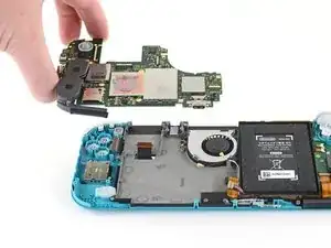
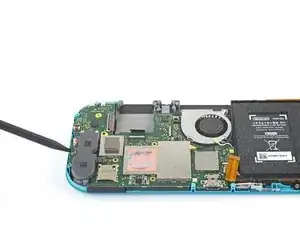
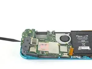
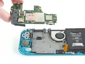
Inserta un spudger en el espacio entre el marco y la placa base y levanta la placa base para sacarla de su hueco.
-
Retira el conjunto de la placa base.
-


Para volver a armar tu dispositivo, sigue estas instrucciones en orden inverso.
Lleva tus desechos electrónicos a un centro de reciclaje certificado.
¿La reparación no salió según lo planeado? Prueba algunas soluciones de problemas básicos, o pide ayuda a nuestra Comunidad de respuestas de Nintendo Switch Lite.

All my screws got stripped any ideas on how to remove?
Almost A Mammal -
A Y0 screwdriver seemed to work better for me.
Tommy Morrill -
What type of screw driver do I use to un screw the screws and which way
Luca Capito -