Introducción

He notado que comencé a tener problemas para arrastrar ventanas. Al principio pensé que era un problema de software ya que recientemente cambié de sistema operativo Windows a Linux. Pero el problema persistía en ambos sistemas operativos, por lo que estaba claro que se trataba de un problema de hardware.

Así es como comenzó la saga del desmontaje del mouse trackball. ¡¡¡El resto es historia!!!

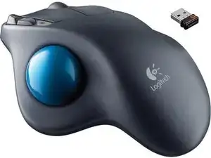
Esta guía te ayudará a desarmar tu propio Logitech M570 y te guiará a través del reemplazo del interruptor. Ten en cuenta que necesitarás habilidades de soldadura para reemplazar los interruptores. Es posible que te las arregles sin habilidades de soldadura si está buscando reemplazar el sensor de bola.

  1. tCIvnP4HVVHEvnTN
    tCIvnP4HVVHEvnTN
    wdhSsaBIL3tcuKpO
    itFyN2tARaPe64RD
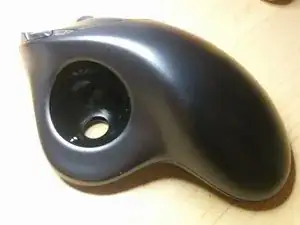
    • Retira la bola de seguimiento

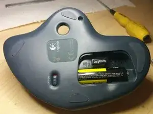
    • Gira el interruptor de encendido a la posición de apagado

    • Abre la tapa de la batería

    • Retira la batería AA

    wat is het nummer voor de vervanging van de zender in de muis?

    J. Tillie -

  2. X4KJZSYUaoUMBg1J
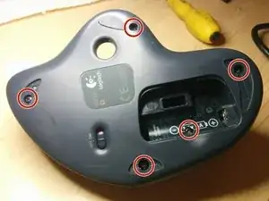
    • Retira 3 almohadillas como se muestra en la imagen.

    • Desatornilla los 5 pernos con un destornillador Phillips n.º 1

    • El último tornillo está oculto debajo de la etiqueta de la batería. Tendrás que hacer un agujero para llegar a él.

    Partly lifting up the battery label from the left-hand side also worked for me. :)

    Henrik Hille -

    My rubber pad came off fairly easy (pinch them and slowly remove) and the adhesive remained on the pads, making it easy to replace them at the end.

    Erik G -

  3. k5fyG5NJPt4ZQySU
    k5fyG5NJPt4ZQySU
    PVB5GyHYSRvvFZUy
    SEpmlkRrjBqLxThX
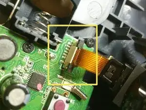
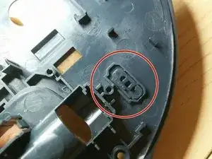
    • Levanta el pestillo y extrae el circuito flexible del conector. Desconecta el sensor de bola de seguimiento.

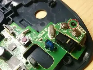
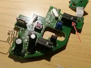
    • Desenrosca el primer tornillo y separa el pequeño PCB

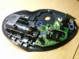
    • Saca los otros 3 tornillos. El último tornillo está escondido detrás de un condensador en la imagen.

  4. DQjHqgQFxlr1sXRS
    DQjHqgQFxlr1sXRS
    6i4CRTIWKAMecS5J
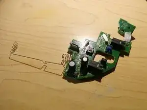
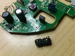
    • Retira con cuidado la placa de circuito impreso. Ten cuidado de no doblar el conector de la batería.

    • Retira el interruptor de alimentación. De lo contrario, podría caerse y no volver a verlo nunca más...

  5. QSX2mTHr1NZOqSTQ
    QSX2mTHr1NZOqSTQ
    wE1DTKtTtZNXaWVM
    RXL4yyiiB2XHMCn2
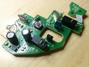
    • Como puedes ver, uno de los interruptores está completamente roto. ¡Tiene que ser reemplazado!

    • Hay pocos repuestos disponibles. He usado este. Pero es posible que desees utilizar uno original. O el del rival.

    • Realmente no importa mucho. La diferencia es la fuerza operativa. El original viene con 75 gf que da una acción de clic más ligera. Pero opté por 150 gf para el reemplazo, ya que deberían durar más...

    • Saca los interruptores viejos. ¡Puede ser un poco complicado! Es posible que desees utilizar varios soldadores para calentar los 3 pines a la vez. O pistola de calor. La decisión es tuya. ¡Solo ten cuidado de no quemarte! Para su información, ¡probablemente este no sea el mejor proyecto para la primera experiencia de soldadura!

    • Suelda nuevos interruptores.

    Thanks for the guide. Just finished successfully changing out the switches in one of my M570’s!

    subpaccdr -

    Great guide. I just did this with 3 M570’s that all had issues with the left click.

    This was my first real experience soldering, and I used a cheap solder sucker to help get the old microswitches out. It was still difficult and I ended up breaking most of the old ones. Once they were out though, putting the new ones in was really easy.

    FYI, the link to the “original” microwitch is not quite right. The M570 uses Chinese Omron D2FC-F-7N, whereas the ones you linked to (which are the ones I used for replacement) are Japanese Omron D2F-01F.

    Mathieu Goodman -

    Seems to have worked well. I used an iron with a “angled chisel” shaped tip which reached two of the wires at a time and walked the old microswitch out and then the new one back in. First of all, I wicked off the old solder with a bit of fine multi-strand wire from a bit of old phone of extension cable. I gave up on applying various contact cleaners etc. and gave in an bought some microswitches - I just had a look in my Cordless Trackman Wheel and they are the same switches but it is a bit more involved to get to the board where the microswitches are located. Since it is still clicking well I just put some contact lubricant (Power-Lube PL-64) on them. Be careful on reassembly to get the spring on the wheel back in place (when you open it the wheel may stay in the upper part of the casing - don’t loose the spring - to put it back - first position the wheel in place in circuit board.

    Christopher -

    You don’t need to get a solder sucker as Mathieu suggests - look out a bit of fine multi-strand wire (old phone extension cables - the flexible ones that go from the wall socket to the phone) will do fine as a solder wick. - Flux does help - a “no mess” one is the best to use - microscopic amounts.

    Christopher -

    What about the micro switch with the red button, mine isn't working properly when I press down on the wheel, what part number would that be?

    Alucard6X -

    I switched out my switch with the one you recommended yet it is too tall, and closing the case causes the switch t be rendered useless, maybe I did’’t get the switch all the way in. Maybe you have a fix?

    Dylan Church -

    Either you have not installed it flush to the PCB or possibly you have it in backwards. If it is in correctly, check to ensure the PCB is mating with the power switch correctly. Had one I did that I didn’t check for that and it caused the problem you are having. Easy way to check is try to turn the switch on. Should move relatively easy.

    freemanmarc74 -

    For those in Australia, Jaycar sell a compatible switch, CAT.NO:  SM1036. It comes with a lever attached but it can easily be removed. The operating force required is notably higher than the original.

    Chris Alger -

    I struggled to remove the solder, but was able to easier heat and afterwards remove with a solder sucker after adding some fresh solder (maybe the flux helped). I'm not sure if this is a real technique, but it worked for me.

    I used the switches linked in the guide. They seem to work so far but time will tell if they last a reasonable amount of time.

    Thank you for the guide.

    Erik G -

    Nice write-up, keep working the way you are. I am a fan of wired trackballs and my micro-switch is broken on two of them. Time for surgery.

    Hubert Rodenbaugh Jrq -

Conclusión

Para volver a armar tu dispositivo, sigue estas instrucciones en orden inverso.

Kirill

Miembro Desde 11/04/17

1352 Reputación

18 comentarios

Instructions are very clear and accurate. The most difficult part of this repair is de-soldering the switch, additional information is needed for this step.

Hugo Castro -

Yeah, you either have to use 2 irons to apply heat to 3 pins at the same time. Or take apart body of the switch and cut one of the pins from the body. That way you can use one iron to apply heat to 2 pins at the same time to get it detached from PCB

Kirill -

Folks, use a solder sucker and a solder wick. There should be many articles out there on using solder (extractor) sucker and wick. But basically you melt solder , solder sucker sucks up the most of it (Put the tip right over the end of the metal leg RIGHT after melting) All has to happenen very quickly.

Then the solder wick, you rub over the metal pins using the solder iron to push it along the PCB around the pins and the switch will just drop out.

No offence to any one but the article author did say not advised for your first solder experience, and using solder wick etc would be a veteran solder master trick.

https://www.google.com/url?sa=t&rct=j&q=...

john sloan -

Fine multi-strand wire from an old phone extension cable is good as a wick to remove solder - use a tiny amount of flux to help.

Christopher -

An aside to replacing the switches: if you’re having problems with click bounce and a regular contact cleaner isn’t working you could try an oil for electric model train motor commutators: Peco Electrics Power-Lube PL-64 - I picked up a little in a model shop but you can buy it online in the UK for around £6 to £7 for a couple of mL - the key bounce problems have largely disappeared after one or two applications both for my M570s and for an older cordless trackman wheel that I had given up on. If you have one of these it is worth noting that they will run perfectly well on NiMH rechargeable cells whereas the M570 will not. The latter may win out on simple battery life but on the environmental side: using a rechargeable cell should be better in the longer term especially as the grid gets a higher proportion of renewables.

Christopher -

I have done this repair and right click is now stuck

mike osted -

can some one suggest what switch i should i get im disabled with muscular dystrophy and the buttons are really hard so i need some switch that doesn’t take much force to click

raziel2008 -

What is the size of the Phillips screws on the inside? My smallest driver could handle the case screws, but would not seat in the PCB screws. I want to about getting the wrong driver.

Michael Daly -

Successfully replaced the left trackball switch. Thanks Kirill and others for your excellent pics and tutorial!!

Removed the switch in a defunct trackball and used that as a replacement. A light careful touch is needed throughout. Logitech use lead-free solder so it may take some priming with flux and/or leaded solder for the solder wick to suck. I also used my solder sucker to get the last bit of solder out of the 3 pcb switch holes. As someone mentioned, the plastic on/off switch on the underside of the trackball is now in earth orbit - it took off at high speed after it jumped out of my tweezers. All is not lost - there is an easily accessible slide switch underneath the meteoric plastic switch.

John Ess -

John,

Glad it worked out for you! Happy to contribute to this community!

Cheers,

Kirill -

Excellent tutorial, Kirill! One suggestion: where you talk about removing the main button switches, a photo of the bottom of the board, showing where the switch contacts are soldered, would be even more helpful. Thanks for your very clear instructions and sharing your experience!

Ed Eaglehouse -

The original Switch (Omron D2F-01F) and its slightly heavier cousin (Omron D2F-01) are both rated for low voltage/amperage use (100mA max). Because of this, the contacts are plated with gold. The other 2 switches which are mentioned in this article (Omron D2F and C&K ZMCJF7P0T) are meant for switching larger 3A currents. Because of this, their contacts are coated in a silver alloy.

I say all this because the silver alloy can oxidize over time and prevent reliable contact. That alloy depends on the occasional spark from the higher current to “clean” off this oxide ensuring contact can be made. Using a silver alloy in a low current application will not provide this spark and may prematurely fail. Gold, on the other hand, tends to not oxidize and does not require this “cleaning”.

Long story short, I recommend either of the 2 gold plated switches in this application. Use the original (Omron D2F-01F) if you like a lighter button press or the other (Omron D2F-01) if you prefer a heavier button press.

Null Dev -

Many thanks, Kirill for the excellent walk-through. I have about a 7 or 8 year old M570 that began having the sensitivity issue (frequent “accidental” double click). Definitely did not want to junk the entire thing when the rest of it still seems solid.

FWIW, rather than replacing the switches I simply added two layers of clear tape to the bottom of the button. Seems to be working great for now. We’ll see how that fix holds up with use over time.

Cheers

Seneca Maior -

Thank you for the tutorial Kirill and Seneca for this awesome tip. I had the double click issue too and just a bit of sticky tape on the top of the switch seems to have solved the matter. I too wonder how long it will last - my M570 is about 5 years old.

Wajih Hossenally -

I’ve been needing to clean out my trackball for years and finally found this guide it really helped and now the mouse is as good as new.

scf2312 -

The instructions are very easy to follow. The only difficulty was with removing the switches. Even after removing the solder I had to pry the switches out. The circuit board was scratched but thankfully the mouse still works.

Gin -

For what it might be worth, Digikey.com reports the “lifetime” specs, in terms of electrical and mechanical cycles of each recommended switch. The numbers are counter-intuitive: on the face of it, the recommended replacement has less than 1/3 of the expected electrical life of the original, and the rival is half of that.

SwitchID | gramsForce(gf) | Digikey# | ElectricalLife(cycles) | MechanicalLife(cycles)

Recommended | 150 | SW500-ND | 30,000(!) | 1,000,000

“Original” | 75 | SW502-ND | 100,000(!) | 1,000,000

“Rival” | 150 | 401-1742-ND | 15,000(!) | - (not provided)

Sam Shovel -

Omron switches are not available on mouser or digikey, this version is available ZMCJF7P0T

Ace Malik -