Introducción

Esta guía te ayudará a sustituir la carcasa del Joy-Con izquierdo de tu Nintendo Switch (modelo HAC-015).

Si la carcasa de tu Joy-Con está agrietada o muestra decoloración, es posible que quieras reemplazarla. La carcasa del Joy-Con protege sus componentes internos y le da un aspecto estético. Una carcasa dañada acabará dañando los componentes internos y también puede hacer que sea incómodo jugar.

Puedes encontrar carcasas de repuesto en Amazon, donde son mucho más baratas que comprarlas a través de Nintendo. Vienen en muchos colores y diseños diferentes.

Cuando sigas los pasos, asegúrate de no arrancar ningún tornillo ni retirar ningún componente utilizando demasiada fuerza. Cualquier pequeño daño puede hacer que tu Joy-Con no funcione después de volver a montarlo.

Si también quieres reemplazar la carcasa del Joy-Con derecho, hay una guía útil en iFixit que puede guiarte a través de ese proceso.

  1. b5coIjciEm6YXOXx
    b5coIjciEm6YXOXx
    yoxiQFnvilyUUmeP
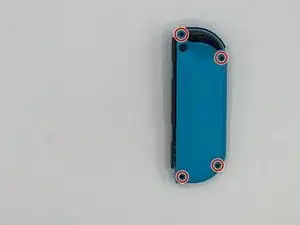
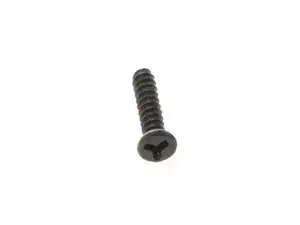
    • Desatornilla los cuatro (4) tornillos tri-wing ("Y00") del panel trasero. (Se recomienda guardarlos en un lugar seguro)

  2. NVtbrSokfYsVjoEQ
    NVtbrSokfYsVjoEQ
    mCTgSXiuMZhb4dem
    YbA5HtHJ5GDneDZC
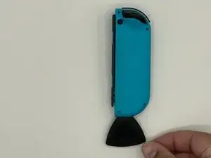
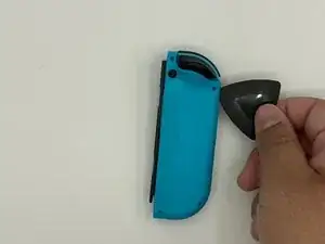
    • Inserta una púa de apertura en el reborde del borde inferior del mando (frente a los botones L y ZL).

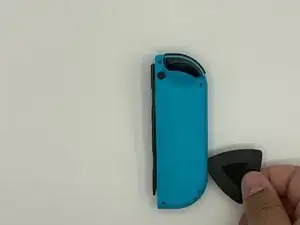
    • Desliza lentamente el borde plano de tu púa de apertura hacia el lado del Joy-Con.

  3. LwlLVNRoDXquQiOh
    LwlLVNRoDXquQiOh
    Yawr1RDyfFWlcawv
    • Con el carril de carga de espaldas a ti, abre el Joy-Con como si fuera un portátil.

    • No retires aún por completo el panel trasero; todavía hay dos cables planos que conectan la barra de carga con la placa madre..

  4. AlfR4Df4iuZfavrB
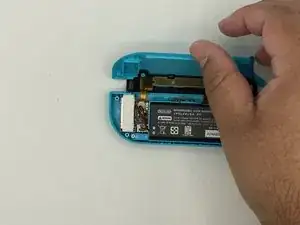
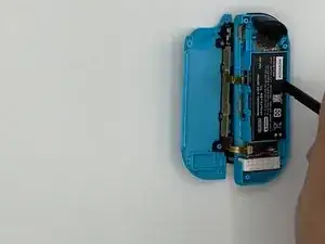
    • Con una palanca, extrae el conector de la batería de su alojamiento en la placa madre. Esto evitará que el Joy-Con se encienda durante la reparación.

    • Ten cuidado cuando trabajes alrededor del cable del motor de vibración que pasa cerca del conector de la batería.

  5. xLfdJHhqkRcQoQCM
    xLfdJHhqkRcQoQCM
    o3qgiTMIBDgrEgNe
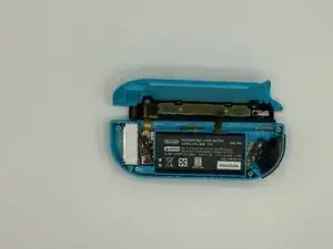
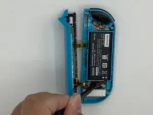
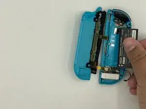
    • Inserta un spudger entre la batería y la carcasa de los Joy-Con.

    • Haz palanca con cuidado para sacar la batería, que está ligeramente pegada en su sitio.

    • Ten cuidado de no deformar o perforar la batería.

  6. PvACKOGpq166qArM
    • Retira los tres (3) tornillos Phillips #00 dorados de 3½mm del bastidor central.

  7. O1BVHVbJQy5fFqTA
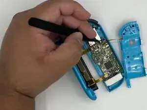
    • Dé la vuelta con cuidado al marco intermedio, alejándolo de la placa base, como si estuvieras pasando la página de un libro.

    • Los cables planos son extremadamente frágiles.

  8. WvNafavxDB6aUZTv
    WvNafavxDB6aUZTv
    IeFdYnCwmP4JC3F6
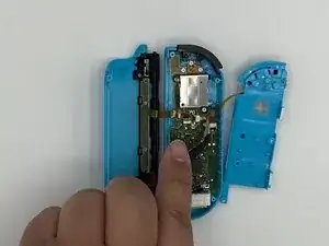
    • Utiliza unas pinzas para voltear el bloqueo del conector ZIF opuesto al cable.

    • El botón ZL está bloqueado en su lugar por un pequeño conector ZIF en la placa base.

    • Utiliza unas pinzas para sacar suavemente el cable flexible del botón ZL de su conector ZIF. El marco intermedio está ahora desconectado y puede ser retirado.

  9. x2ELyImMI4ajeNMP
    x2ELyImMI4ajeNMP
    vDqeivuOXeRvYrSY
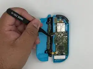
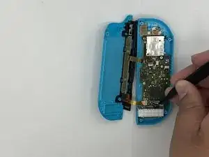
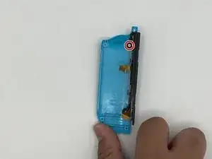
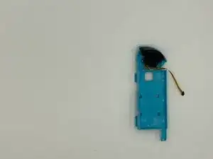
    • Desbloquea el conector ZIF superior del raíl y desconecta el cable.

    • Desbloquea el conector ZIF inferior del raíl y desconecta el cable. Ahora podemos retirar el raíl del bastidor trasero.

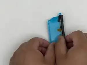
    • Retira el borón ZL y su muele.

    • Ten cuidado porque el muelle tiende a soltarse.

    Details for removing the ZL trigger are Step 12

    Luke Lucas -

  10. 6m56f4BKPWTQGVN2
    6m56f4BKPWTQGVN2
    PPo4YBtWCMdsJaXL
    PU4uocWTAjJR3Wty
    • Retira el tornillo que sujeta la barandilla. Retire la barandilla del bastidor trasero y déjela a un lado.

    Screw is Philips #00 as well

    Doc Halstater -

  11. AZGx6ZuWkqoBv5gW
    • Retira el botón de cierre y déjelo a un lado.

  12. 3nTkswaKYUADclih
    3nTkswaKYUADclih
    TnoxA1dRSJdVmFE6
    • Presiona el pestillo situado debajo del gatillo con unas pinzas. Retira el gatillo con cuidado.

    • Asegúrate de anotar la posición de los dos muelles situados debajo del gatillo, ya que deberán volver a colocarse en el mismo lugar en el nuevo bastidor central.

  13. ehlggYmVsBpUTYMr
    ehlggYmVsBpUTYMr
    jUGp232rXjufQxeX
    • Quitar el tornillo que sujeta la placa de circuitos para el gatillo en su lugar.

    • Retira la placa del circuito.

  14. jyvAkZdrM4mG4g24
    jyvAkZdrM4mG4g24
    oKFNQTWWUxbwqfPe
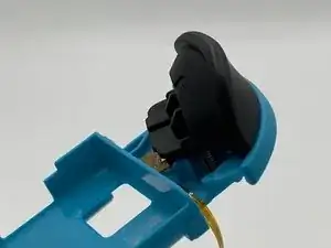
    • Retira los tornillos que sujetan el joystick.

    • Desbloquea el conector ZIF y retire el cable plano con unas pinzas.

    Unlock the ZIF connector and release the ribbon on the left that is covering a screw before attempting to remove the screws

    Luke Lucas -

  15. GYOLho24y4pMUNIi
    GYOLho24y4pMUNIi
    oEgjnviILWoJw1hs
    • Retira el joystick.

  16. cWVFKBZZ2XsUCWog
    cWVFKBZZ2XsUCWog
    AwnKCBKAPyQNFoFL
    ZokQHYefNPKqksK2
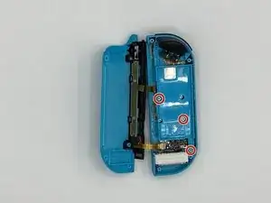
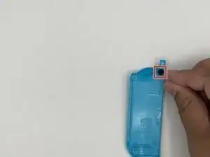
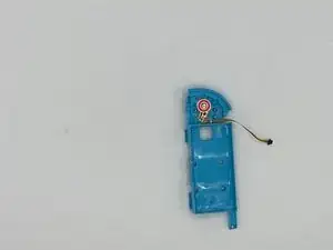
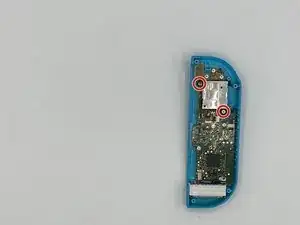
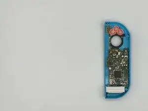
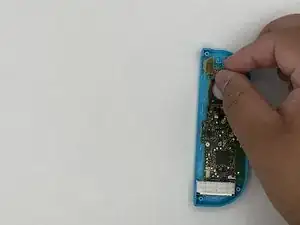
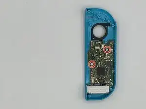
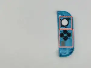
    • Retira los tornillos que sujetan la placa flex (marcada con un círculo rojo) para los botones menos y L.

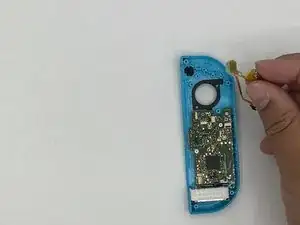
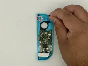
    • Retira el circuito flex.

  17. 6adyooKy3XsRtpgW
    • Retira el botón mens.

    • Habrá una cubierta de goma sobre el botón menos. Asegúrese de ponerlo sobre el botón menos durante el reensamblaje.

  18. BgBuGfAMwMtWOiPX
    • Retira los tornillos que sujetan la placa madre.

  19. iLjRd6qI4cALUa34
    iLjRd6qI4cALUa34
    AN6broLjJkiIJLTf
    2PJtLPrPsEdvoBVg
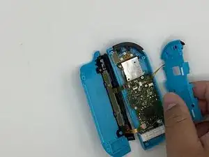
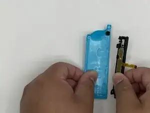
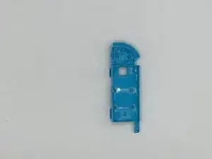
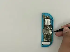
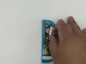
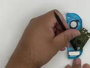
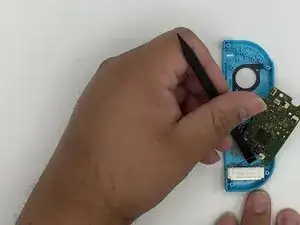
    • Haz palanca suavemente con el spudger para extraer el rumble pack de su alojamiento.

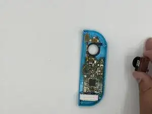
    • Retira el rumble pack y la placa madre.

  20. eL6gqGdSYOwLvWKy
    • Retira los cinco botones restantes de la carcasa.

Conclusión

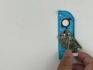
Para volver a ensamblar tu dispositivo, sigue estas instrucciones en orden inverso.

Jose Castro

Miembro Desde 16/01/20

873 Reputación

10 comentarios

This guide was very helpful! A picture of the latch location on the trigger (step 12) would have been a big help, that step took a minute because I was putting pressure on the wrong spot.

I also noticed that most of the #00 screws were more receptive to a J00 bit. Might be worth noting in the tools section since swapping between them can strip a screw.

Fitz Montville -

Used this guide for reference on the tools needed, someone else pointed out to use the J00 bit instead of the P00 and I’ll second that as the fit for the screws was much better, thanks for the guide much appreciated!

Lee Whittaker -

Exactly what I needed! Dropped a set of controllers on a tile flow and the rail popped out and pulled the ribbon cables too. I picked up another iFixit toolkit with some J bits to put it back together. I don’t know why I waited this long to fix it. Charged the controllers overnight and I’m up another set now!

energy96 -

Others above have mentioned that they needed to use a J00 bit instead of P00, but mine did not work with a J00 and was better with a P000

Jeremy Johnson -

Small thing. In the tools list, it incorrectly says Y0 while the rest of the post correctly says Y00 for the back screws.

William Doering -

Thanks!

Just need a review for add the instructions for removing the L button, between steps 8 and 9 ;)

kazulius -

Nicht ohne Lupe, Pinzette und Spudger als Brillenträger an diese Reparatur gehen. Die Verbindungen der Flachkabel sind verdammt klein. Eine Gute Anleitung. Hat bei mir funktioniert!

Gerd Paßmann -

I followed these instructions and everything works perfectly except my Switch doesn't think the joycon is attached anymore; it thinks I'm using it wirelessly even though it's docked into the system. Any advice?

Dani Watson -

Please help...

So I followed the instructions step by step, however now the left joy con does not want have a connection status on the switch, it thinks it is disconnected.

Leonard -

Great guide, used it to mod my shell and replace the thumbstick at the same time. The only thing I would say is that if you are replacing the rail and slide locks you'll need a bit of extra guide via YT or something (not sure if there is one on here.) As others have said 'depress the latch' for the ZL button is tricky (kind of just pulled about on mine until it came off, still not sure where the latch is.) And one final thing, it says ZL button at one point but ZL is a trigger - they mean the Z button. But again, great guide, far less issues than expected - thank you to the author.

Luke Lucas -