
Introducción
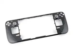
Usa esta guía para quitar o reemplazar la carcasa frontal (cubierta frontal) en una Steam Deck.
Recuerda: seguir los procedimientos de seguridad contra descargas electrostáticas (ESD) generales mientras reparas tu dispositivo.
Este procedimiento implica un desmontaje casi completo, incluida la extracción de la pantalla. Sabes en lo que te estás metiendo. Necesitarás adhesivos de repuesto para la pantalla y los altavoces.
-
-
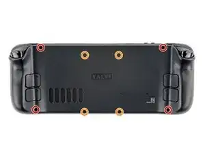
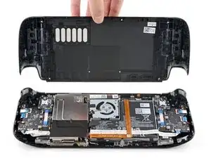
Utiliza un destornillador Phillips para retirar los ocho tornillos que sujetan la tapa trasera:
-
Cuatro tornillos de 9,5 mm
-
Cuatro tornillos de 5,8 mm
-
-
-
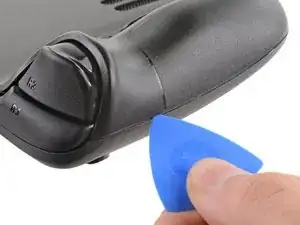
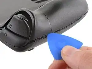
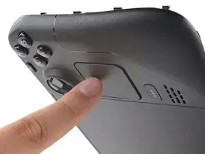
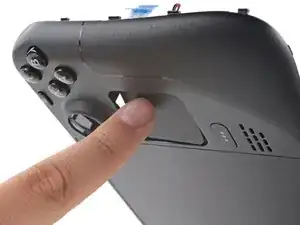
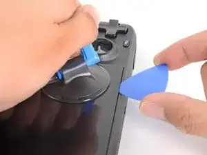
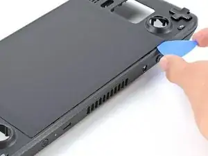
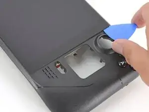
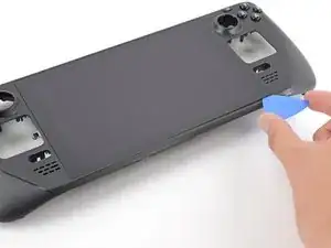
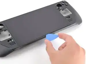
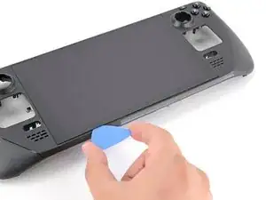
Inserta una púa de apertura en el delgado hueco entre la tapa trasera y la carcasa delantera, a lo largo del borde de la empuñadura derecha.
-
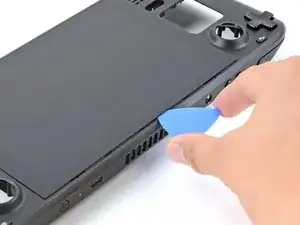
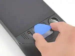
Haz palanca en la tapa trasera para liberarla de los clips de bloqueo.
-
-
-
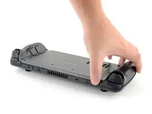
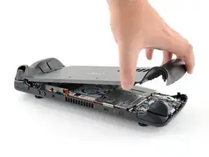
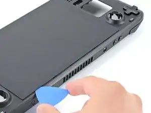
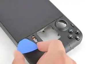
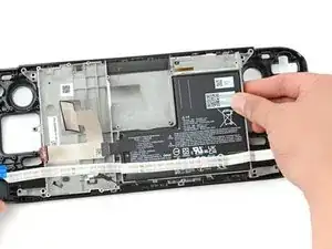
Agarra la tapa trasera por la abertura que acabas de crear y tira de ella hacia arriba y lejos del dispositivo para desenganchar los bordes largos.
-
Retira la tapa trasera.
-
-
-
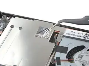
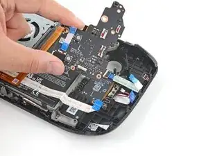
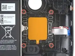
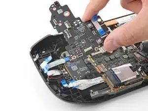
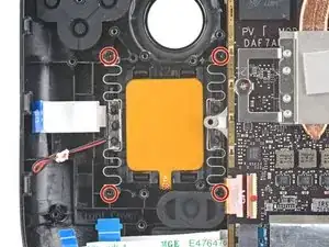
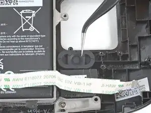
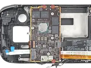
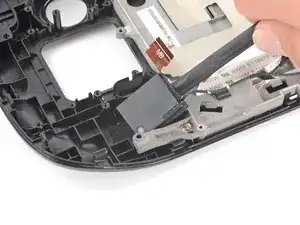
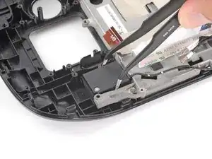
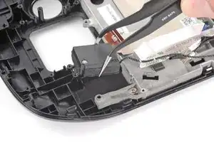
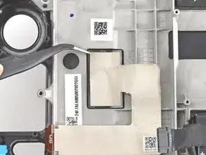
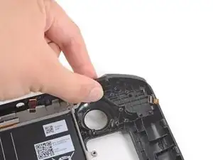
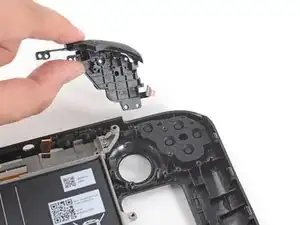
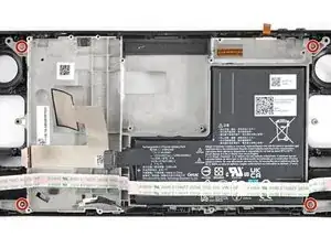
Utiliza unas pinzas para retirar el trozo de cinta adhesiva que cubre el tornillo oculto del escudo de la placa.
-
-
-
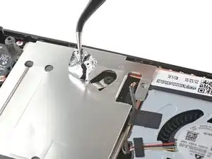
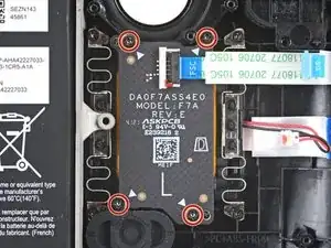
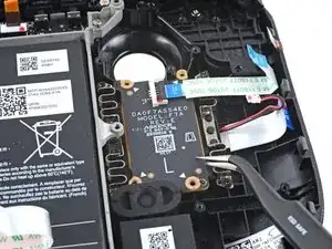
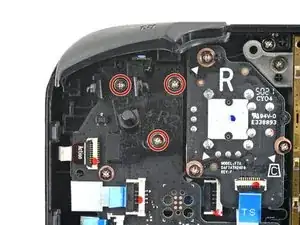
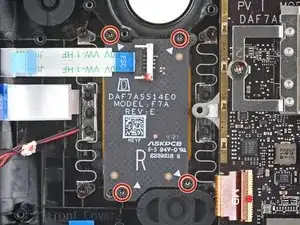
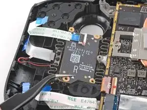
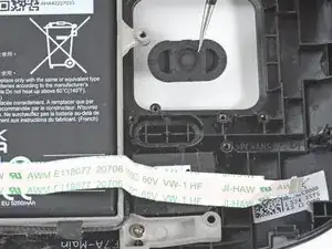
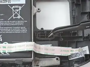
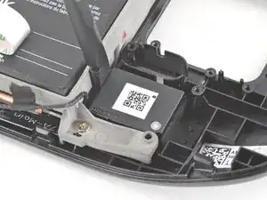
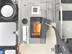
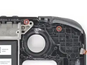
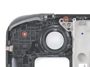
Usa el destornillador Phillips para retirar los tres tornillos que sujetan el escudo de la placa.
-
Un tornillo de 3.4 mm
-
Dos tornillos de 3.7 mm
-
-
-
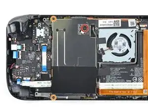
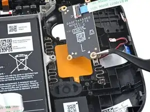
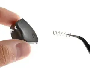
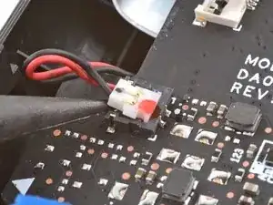
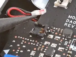
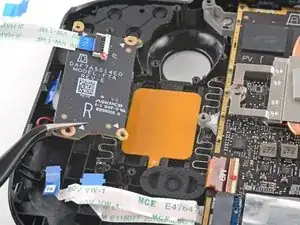
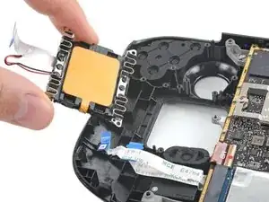
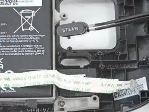
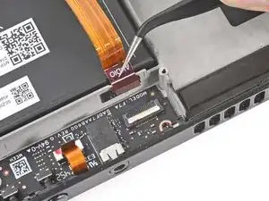
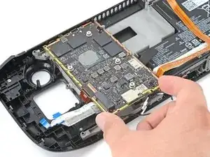
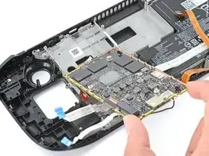
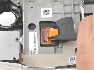
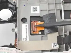
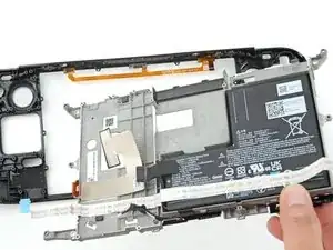
Agarra el cable de la batería por su lengüeta y tira de él directamente hacia fuera de la placa madre para desconectarlo.
-
-
-
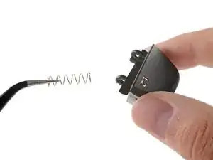
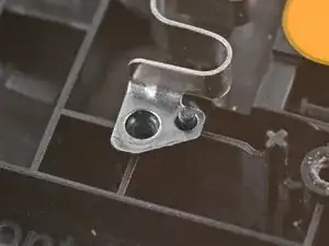
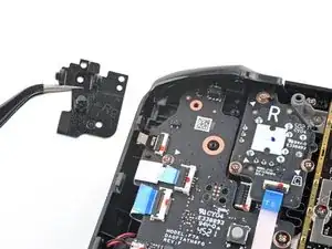
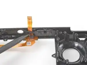
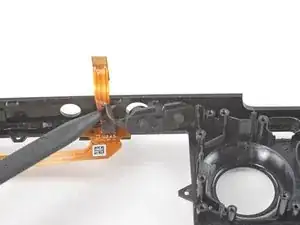
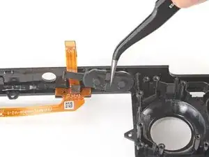
Coloca el extremo plano de un spudger en el borde interior del clip izquierdo del gatillo.
-
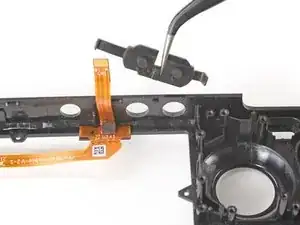
Gira el clip del gatillo hacia afuera y hacia arriba de la clavija para desbloquearlo.
-
-
-
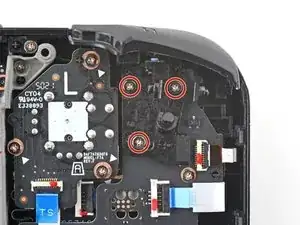
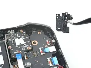
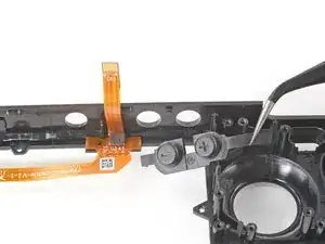
Usa un destornillador Phillips para quitar los tres tornillos de 5,2 mm que sujetan el soporte del gatillo izquierdo.
-
-
-
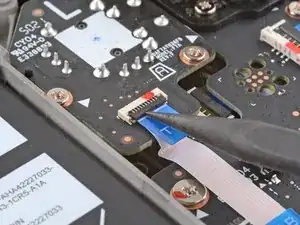
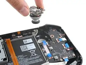
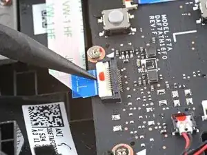
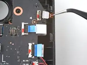
Usa el extremo puntiagudo de un spudger para levantar la pequeña solapa de bloqueo en el conector ZIF del cable del stick analógico.
-
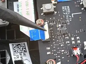
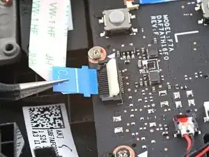
Usa un par de pinzas, para sacar el cable de su conector.
-
-
-
Usa un destornillador Phillips, para quitar los tres tornillos de 5,2 mm que sujetan el stick analógico.
-
-
-
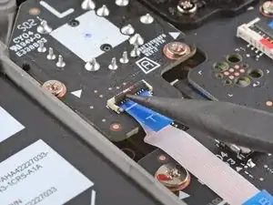
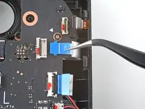
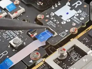
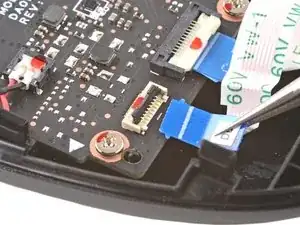
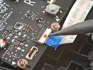
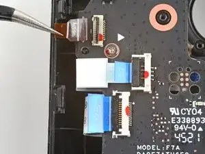
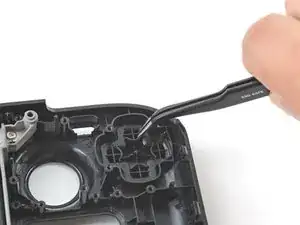
Usa el extremo puntiagudo de un spudger, para levantar la pequeña solapa de bloqueo en el conector ZIF del cable de interconexión del tablero de botones.
-
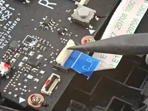
Usa un par de pinzas para sacar el cable de su conector.
-
-
-
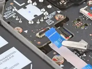
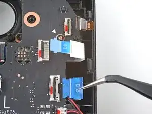
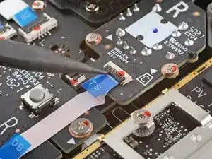
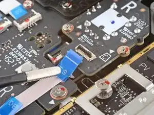
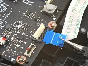
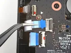
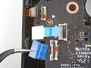
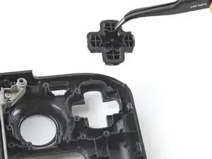
Usa el extremo puntiagudo de un spudger, para levantar las pequeñas aletas de bloqueo en el resto de los conectores ZIF del tablero de botones. Usa un par de pinzas para sacar los cables de sus conectores:
-
Desconecta el cable D-pad.
-
Desconecta el cable de la placa del panel táctil.
-
Desconecta el cable del panel táctil.
-
-
-
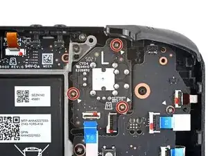
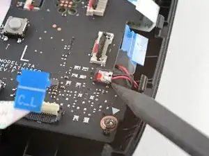
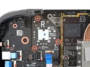
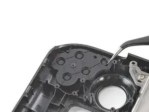
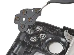
Usa un destornillador Phillips, para desconectar los cuatro tornillos que sujetan el tablero del botón izquierdo:
-
Tres tornillos de 5,2 mm
-
Un tornillo de 3,9 mm
-
-
-
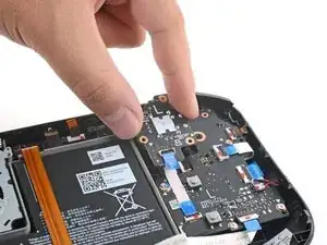
Utiliza un destornillador de tipo Phillips para retirar los cuatro tornillos de 4.7mm que fijan la placa del panel táctil.
-
-
-
Utiliza un destornillador de tipo Phillips para retirar los cuatro tornillos de 4.7mm que fijan el panel táctcil.
-
-
-
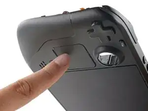
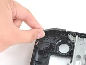
Desde el frente de Steam Deck, usa tu dedo para empujar el panel táctil izquierdo hasta la mitad a través de la cubierta frontal para sacarlo.
-
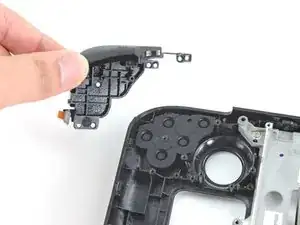
Levanta el panel táctil desde debajo de la sección sobresaliente del marco medio.
-
Retira el panel táctil.
-
-
-
Coloca el extremo plano de un spudger en el borde interior del clip derecho del gatillo.
-
Gira el clip del gatillo hacia fuera, alejándolo y levantándolo de la clavija para desengancharlo.
-
-
-
Utiliza un destornillador Phillips para quitar los tres tornillos de 5,2 mm, que sujetan el soporte derecho del gatillo.
-
-
-
Usa el extremo puntiagudo de un spudger, para levantar la pequeña solapa de bloqueo en el conector ZIF del cable del stick.
-
Usa un par de pinzas, para sacar el cable de su conector.
-
-
-
Usa un destornillador Phillips, para quitar los tres tornillos de 5,2 mm que sujetan el stick analógico.
-
-
-
Usa el extremo puntiagudo de un spudger, para levantar la pequeña solapa de bloqueo en el conector ZIF del cable del tablero de botones.
-
Usa un par de pinzas, para sacar el cable de su conector.
-
-
-
Usa el extremo puntiagudo de un spudger, para levantar la pequeña solapa de bloqueo en el conector ZIF del cable de interconexión del tablero de botones.
-
Usa un par de pinzas, para sacar el cable de su conector.
-
-
-
Usa el extremo puntiagudo de un spudger, para levantar las pequeñas aletas de bloqueo del resto de los conectores ZIF del tablero de botones. Usa un par de pinzas, para sacar los cables de sus conectores:
-
Desconecta el cable de los botones de acción.
-
Desconecta el cable de la placa del panel táctil.
-
Desconecta el cable del panel táctil.
-
-
-
Usa un destornillador Phillips, para sacar los cuatro tornillos que sujetan el tablero del botón derecho:
-
Tres tornillos de 5,2 mm
-
Un tornillo de 3,9 mm
-
-
-
Utiliza un destornillador Phillips para quitar los cuatro tornillos de 4,7 mm que sujetan la placa del panel táctil.
-
-
-
Utiliza un destornillador Phillips para quitar los cuatro tornillos de 4,7 mm que sujetan el panel táctil.
-
-
-
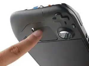
Desde el frente de Steam Deck, usa tu dedo para empujar el panel táctil derecho hasta la mitad a través de la cubierta frontal para sacarlo.
-
Levanta el panel táctil desde debajo de la sección sobresaliente del marco medio.
-
Retira el panel táctil.
-
-
-
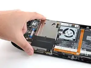
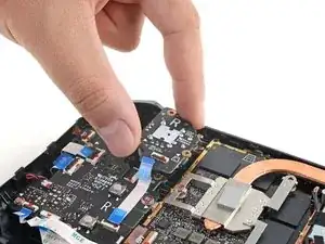
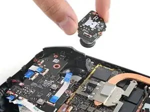
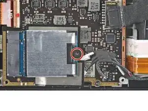
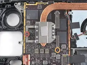
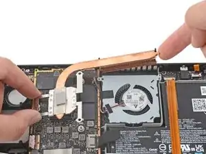
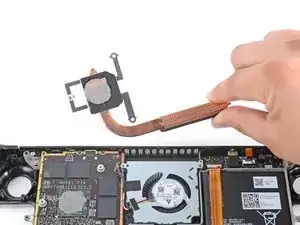
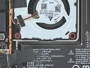
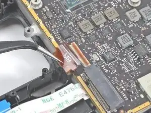
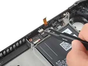
Usa un destornillador Phillips para aflojar y quitar los dos tornillos que sujetan el disipador de calor a la placa base:
-
Un tornillo cautivo de 3,5 mm
-
Un tornillo de 3,4 mm
-
-
-
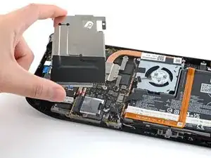
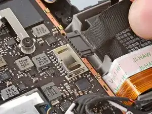
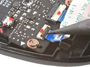
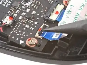
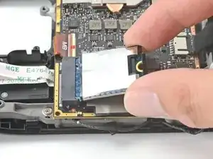
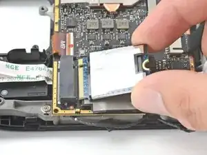
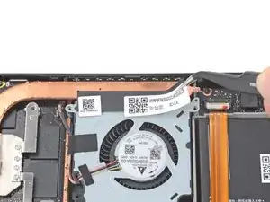
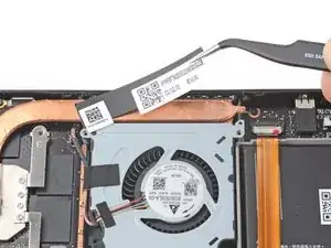
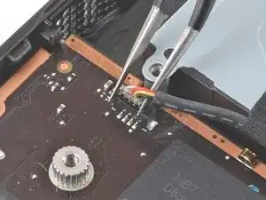
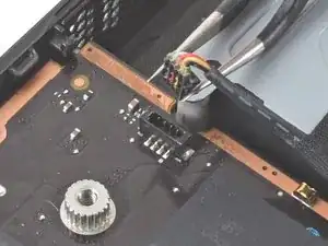
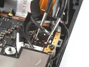
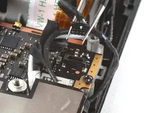
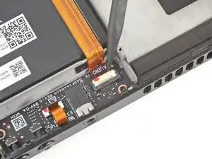
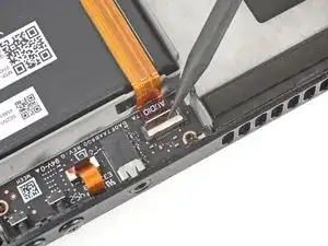
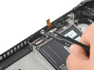
Usa un par de pinzas para sujetar los bordes del conector del ventilador y tira hacia arriba para desconectarlo de la placa base.
-
-
-
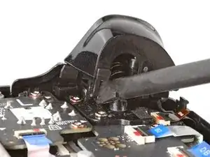
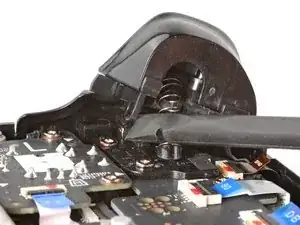
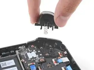
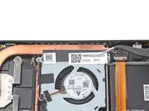
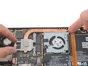
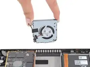
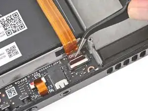
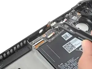
Usa un destornillador Phillips para quitar los dos tornillos de 3,7 mm que sujetan el ventilador.
-
-
-
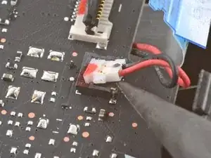
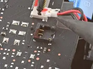
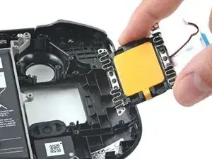
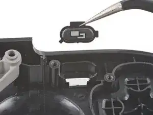
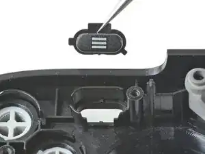
Usa un par de pinzas para sujetar los bordes del conector del altavoz y tira hacia arriba para desconectarlo de la placa base.
-
-
-
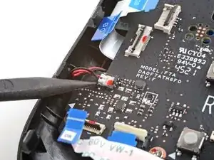
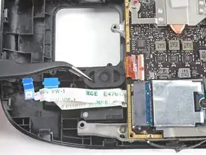
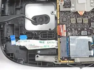
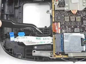
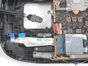
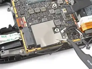
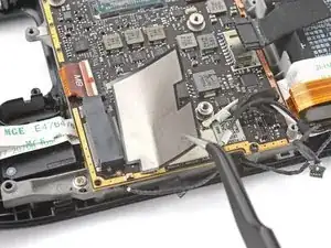
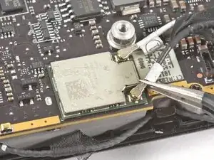
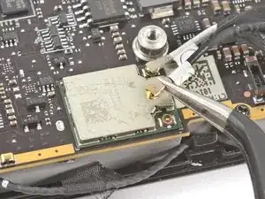
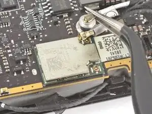
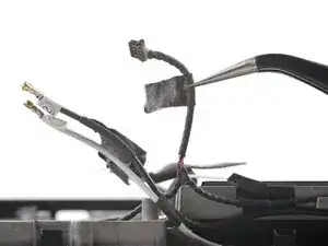
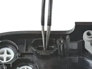
Usa un par de pinzas para agarrar el conector de la antena cerca de su base.
-
Tira hacia arriba para desconectar el cable.
-
Repite para el segundo cable de antena.
-
-
-
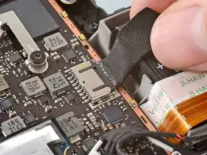
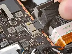
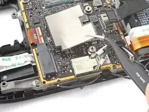
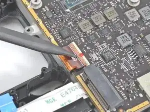
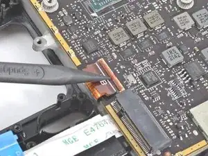
Usa el extremo puntiagudo de un spudger para levantar la pequeña solapa de bloqueo del conector ZIF del cable de la pantalla.
-
Usa un par de pinzas para deslizar el cable fuera de su conector.
-
-
-
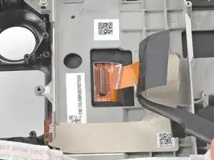
Usa el extremo puntiagudo de un spudger para levantar la pequeña solapa de bloqueo del conector ZIF del cable de audio.
-
-
-
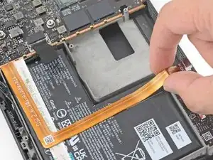
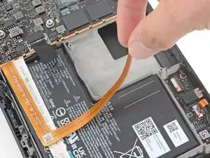
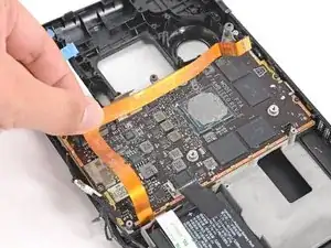
Retira con cuidado el cable de audio de la batería.
-
Si el adhesivo se resiste, no fuerces el cable. Calienta ligeramente el cable de audio con un iOpener o un secador de pelo para ablandar el adhesivo.
-
-
-
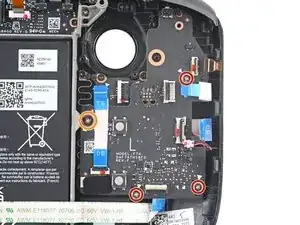
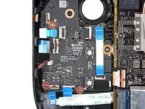
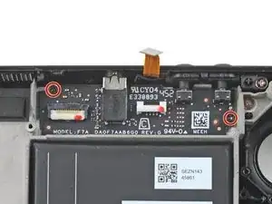
Utiliza un destornillador Phillips para quitar los tres tornillos de 3,7 mm que sujetan la placa base.
-
-
-
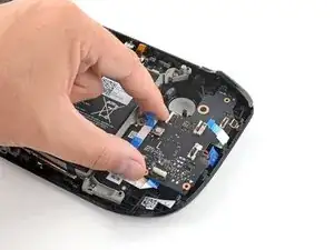
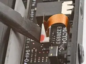
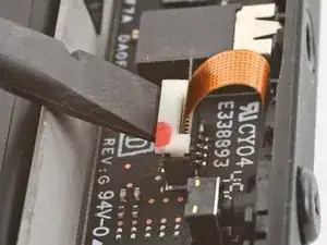
Usa el extremo puntiagudo de un spudger para levantar la lengüeta de bloqueo blanca del cable del micrófono.
-
Usa un par de pinzas para tirar del cable del micrófono hacia arriba y sacarlo de su conector.
-
-
-
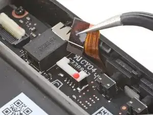
Utiliza un destornillador Phillips para quitar los dos tornillos de 3,7 mm que sujetan la placa de audio.
-
-
-
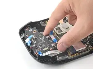
Usa un par de pinzas para sujetar la placa de audio por el conector para auriculares.
-
Pivota el tablero hacia arriba y fuera de su hueco para quitarlo.
-
-
-
Usa un par de pinzas para despegar la cinta que une el cable del altavoz a los cables de la antena Wi-Fi.
-
-
-
Usa un par de pinzas para despegar las diversas tiras de cinta negra que enrutan el cable del altavoz a lo largo del borde inferior del chasis.
-
-
-
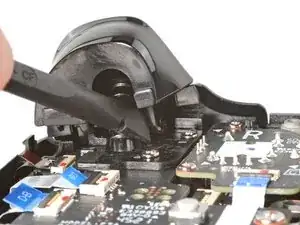
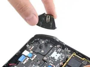
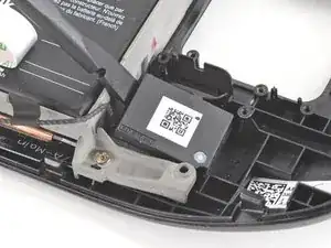
Inserta el extremo plano de un spudger entre el altavoz derecho y el marco.
-
Gira el spudger hacia arriba para separar el altavoz del adhesivo ligero que lo sujeta contra la carcasa frontal.
-
-
-
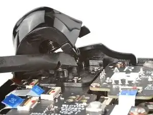
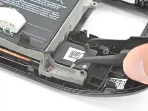
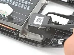
Inserta el extremo plano de un spudger entre el altavoz izquierdo y el marco.
-
Gira el spudger hacia arriba para separar el altavoz del adhesivo ligero que lo sujeta contra la carcasa frontal.
-
-
-
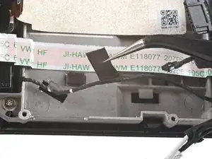
Usa el extremo puntiagudo de un spudger para levantar la pequeña solapa de bloqueo del conector ZIF del cable de la pantalla.
-
Usa un par de pinzas para deslizar el cable fuera de su conector.
-
-
-
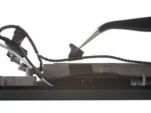
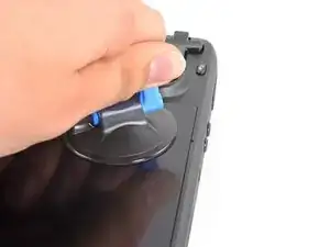
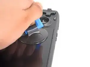
Aplica una ventosa en la esquina superior izquierda de la pantalla presionándola para crear succión, lo más cerca posible del borde.
-
Tira hacia arriba de la ventosa con fuerza firme y constante para crear un espacio entre la pantalla y el marco.
-
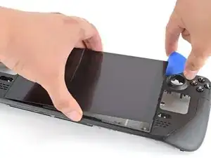
Inserta la punta de una púa de apertura en el espacio.
-
-
-
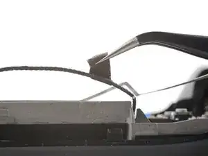
Desliza la púa de apertura a no más de 3 mm de profundidad por el borde superior para cortar el adhesivo.
-
-
-
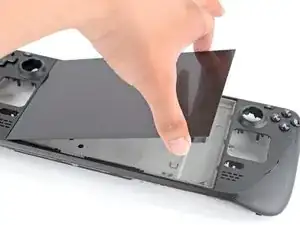
Calienta el borde izquierdo de la pantalla durante un minuto.
-
Desliza la púa de apertura por el borde izquierdo para cortar el adhesivo.
-
-
-
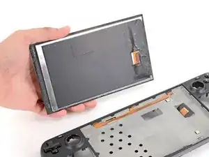
Una vez que hayas cortado el perímetro de la pantalla, levanta con cuidado el borde derecho, abriéndolo como un libro.
-
Retira la pantalla.
-
-
-
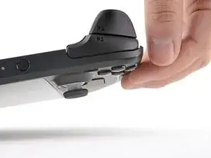
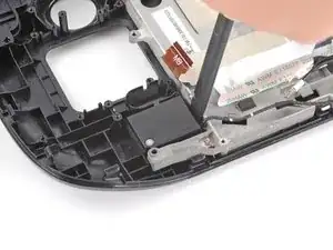
Utiliza un destornillador Phillips para quitar los dos tornillos de 5,2 mm que sujetan el conjunto del parachoques izquierdo.
-
-
-
Utiliza un destornillador Phillips para quitar los dos tornillos de 5,2 mm que sujetan el conjunto del parachoques derecho.
-
-
-
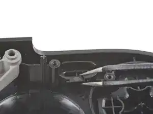
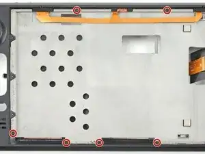
Usa un destornillador Phillips para quitar los seis tornillos de 2,3 mm que sujetan el marco medio a la cubierta frontal, ubicados en el lado frontal.
-
-
-
Usa un destornillador Phillips para quitar los cuatro tornillos de 5,2 mm que sujetan el marco medio a la carcasa frontal.
-
-
-
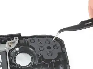
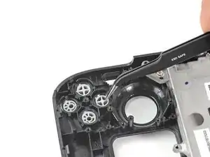
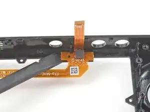
Usa el extremo puntiagudo de un spudger para levantar la solapa de goma a la izquierda de los botones de volumen y sacarla de su clip de plástico.
-
-
-
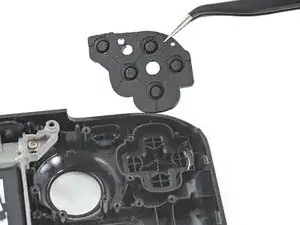
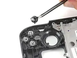
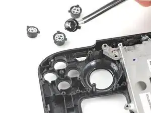
Usa un par de pinzas para quitar los botones de volumen tirando de ellos hacia arriba y hacia afuera de la carcasa frontal.
-
-
-
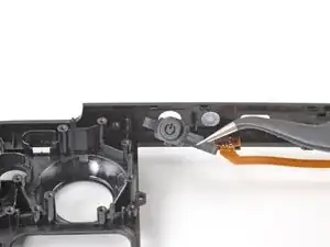
Usa el extremo puntiagudo de un spudger para levantar la solapa de goma a la derecha del botón de encendido y sacarla de su clip de plástico.
-
-
-
Usa el extremo puntiagudo de un spudger para levantar la solapa de goma a la izquierda del botón de encendido y sacarla de su clip de plástico.
-
Retira el botón de encendido.
-
-
-
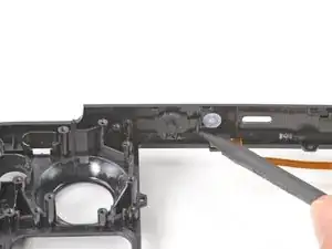
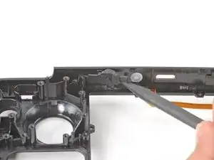
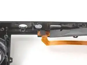
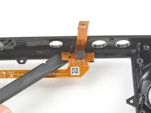
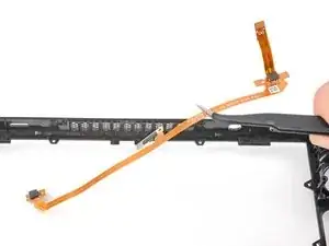
Inserta el extremo plano de un spudger debajo del extremo izquierdo del cable del micrófono y haz palanca hacia arriba para despegarlo de la carcasa frontal.
-
Si el adhesivo se resiste, no fuerces el cable. Calienta ligeramente el cable del micrófono con un iOpener o un secador de pelo para ablandar el adhesivo.
-
-
-
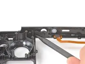
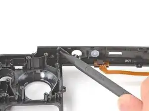
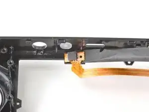
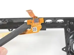
Inserta el extremo plano de un spudger debajo del extremo derecho del cable del micrófono y haz palanca hacia arriba para despegarlo de la carcasa frontal.
-
Si el adhesivo se resiste, no fuerces el cable. Calienta ligeramente el cable del micrófono con un iOpener o un secador de pelo para ablandar el adhesivo.
-


Para volver a armar tu dispositivo, sigue estas instrucciones en orden inverso.
Lleva tus desechos electrónicos a un Reciclador certificado R2 o e-Stewards.
¿La reparación no salió según lo planeado? Prueba algunos soluciones de problemas básicos o solicita ayuda a nuestra Comunidad de respuestas de Steam Deck.

6 comentarios
maybe I don’t need an Atomic Purple replacement shell…
Jon -
Hahaha. Same
Rob -
Same, wouldn't have minded a sweet water dipped or translucent outer shell. Bring back that mad catz/third party aesthetic.
I wanted to replace my old shell with a new one cause it got scratches... well, now I feel the scratches ain't that ugly.
I dropped mine and scratched it.... This seems to involve more than a simple screen replacement on my phones. I'll likely still order some spare parts just in case. With a baby on the way, they will likely break it and I want to be able to fix it quickly.
Fortunately, mine at the moment works. I should always close the hard case. Took it out of the car and didn't zip it up. Fell right out.
Just fell down the stairs and the joysticks damaged the top shell, but everything still works. After reading this, I think I'm going to live with it. Sheesh.