Introducción
Usa esta guía para sustituir la pantalla de tu Steam Deck. El procedimiento es el mismo para las pantallas de cristal grabado estándar y antideslumbrante.
Recuerda: seguir los procedimientos de seguridad contra descargas electrostáticas (ESD) generales mientras reparas tu dispositivo.
Nota: Si instalas un modelo de pantalla de 512 GB en un dispositivo de 64 / 256 GB o viceversa, deberás asegurarte de que también se instala un cable flexible de pantalla adecuado. Ambos tipos de pantallas llegan con sus cables flexibles específicos.
Herramientas
-
-
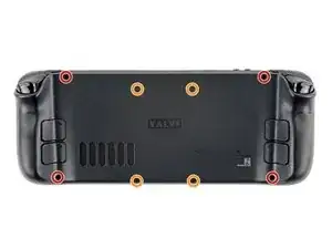
Utiliza un destornillador Phillips para retirar los ocho tornillos que sujetan la tapa trasera:
-
Cuatro tornillos de 9,5 mm
-
Cuatro tornillos de 5,8 mm
-
-
-
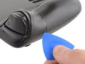
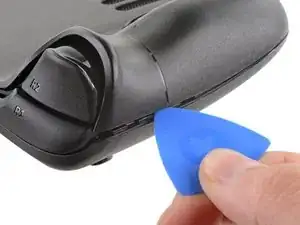
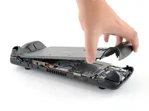
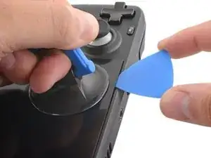
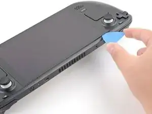
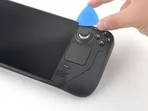
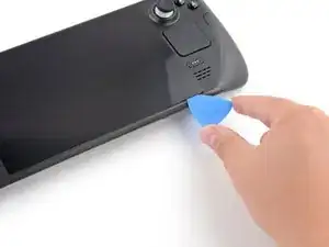
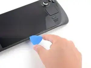
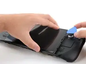
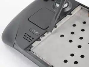
Inserta una púa de apertura en el delgado hueco entre la tapa trasera y la carcasa delantera, a lo largo del borde de la empuñadura derecha.
-
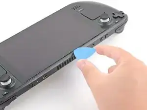
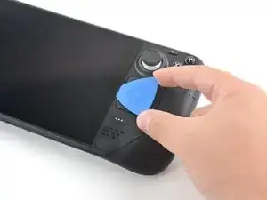
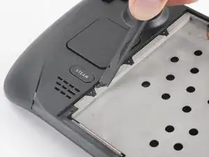
Haz palanca en la tapa trasera para liberarla de los clips de bloqueo.
-
-
-
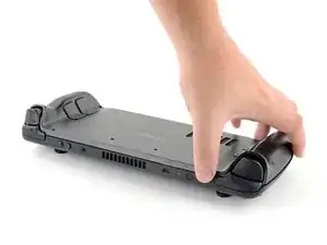
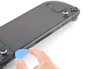
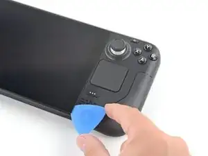
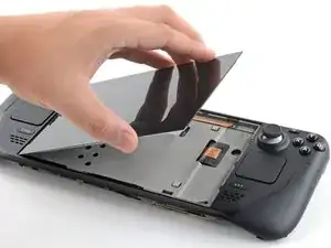
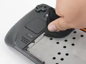
Agarra la tapa trasera por la abertura que acabas de crear y tira de ella hacia arriba y lejos del dispositivo para desenganchar los bordes largos.
-
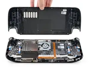
Retira la tapa trasera.
-
-
-
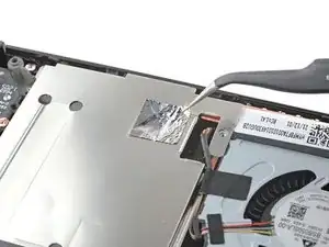
Utiliza unas pinzas para retirar el trozo de cinta adhesiva que cubre el tornillo oculto del escudo de la placa.
-
-
-
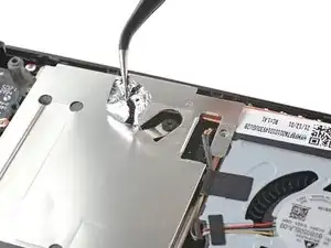
Usa el destornillador Phillips para retirar los tres tornillos que sujetan el escudo de la placa.
-
Un tornillo de 3.4 mm
-
Dos tornillos de 3.7 mm
-
-
-
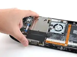
Agarra el cable de la batería por su lengüeta y tira de él directamente hacia fuera de la placa madre para desconectarlo.
-
-
-
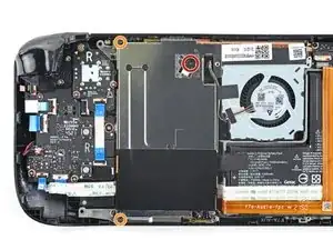
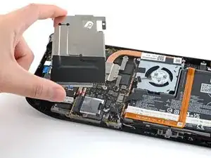
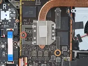
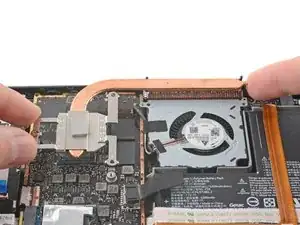
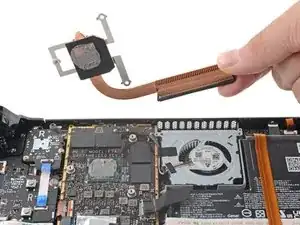
Utiliza un destornillador Phillips para aflojar y retirar los dos tornillos que fijan el disipador a la placa madre:
-
Un tornillo cautivo de 3.5 mm
-
Un tornillo de 3.4 mm
-
-
-
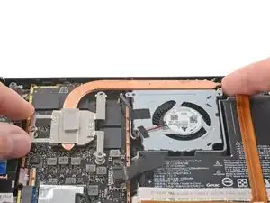
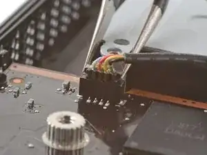
Usa unas pinzas para agarrar los bordes del conector del ventilador y tira hacia arriba para desconectarlo de la placa madre.
-
-
-
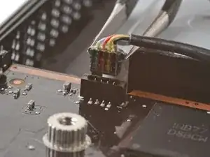
Utiliza unas pinzas para agarrar los bordes del conector del altavoz y tire hacia arriba para desconectarlo de la placa madre.
-
-
-
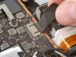
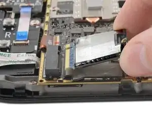
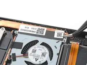
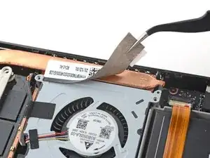
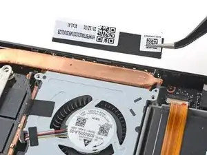
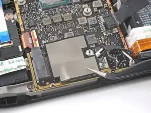
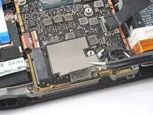
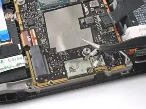
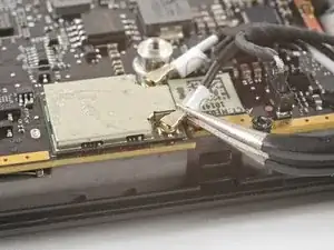
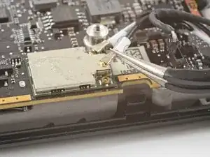
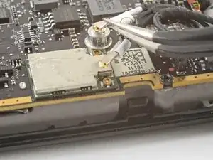
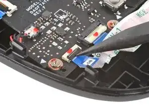
Utiliza unas pinzas para agarrar el conector de la antena cerca de su base.
-
Tira hacia arriba para desconectar el cable.
-
Repite la operación con el segundo cable de antena.
-
-
-
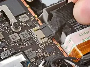
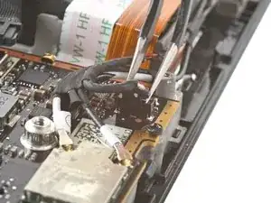
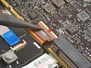
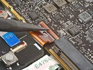
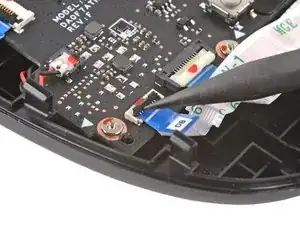
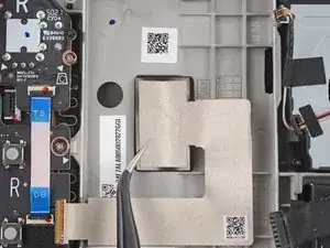
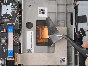
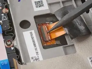
Utiliza el extremo puntiagudo de un spudger para levantar la pequeña solapa de bloqueo del conector ZIF del cable de la pantalla.
-
Utiliza un par de pinzas para deslizar el cable fuera de su conector.
-
-
-
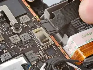
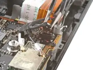
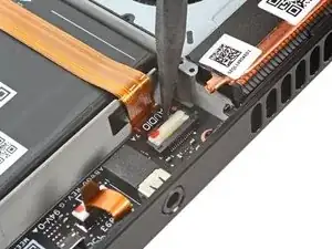
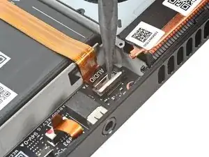
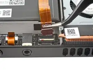
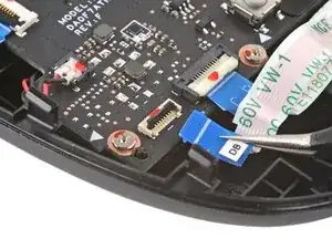
Utiliza el extremo puntiagudo de un spudger para levantar la pequeña solapa de cierre del conector ZIF del cable de audio.
-
-
-
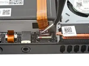
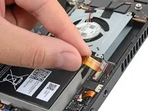
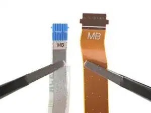
Utiliza el extremo puntiagudo de un spudger para levantar la pequeña solapa de cierre del conector ZIF del cable de la botonera.
-
Utiliza un par de pinzas para deslizar el cable fuera de su conector.
-
-
-
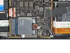
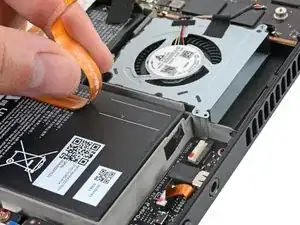
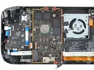
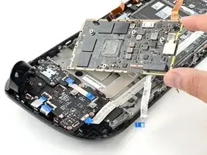
Utiliza un destornillador Phillips para retirar los tres tornillos de 3.7 mm que fijan la placa madre.
-
-
-
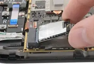
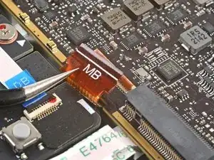
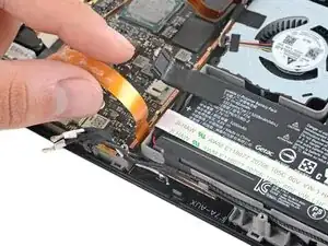
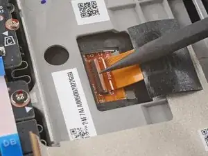
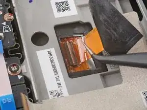
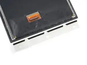
Utiliza el extremo puntiagudo de un spudger para levantar la pequeña solapa de bloqueo del conector ZIF del cable de la pantalla.
-
Utiliza un par de pinzas para deslizar el cable fuera de su conector.
-
-
-
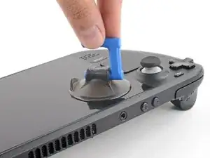
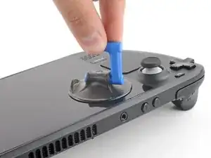
Aplica una ventosa en la esquina superior izquierda de la pantalla presionándola para crear succión, lo más cerca posible del borde.
-
-
-
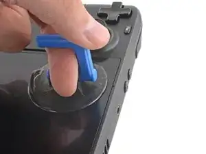
Tira hacia arriba de la ventosa con una fuerza fuerte y constante para crear un hueco entre la pantalla y el marco.
-
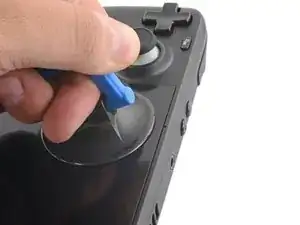
Introduce la punta de una púa de apertura en el hueco.
-
-
-
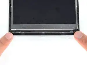
Calienta el borde izquierdo de la pantalla durante un minuto.
-
Desliza la púa de apertura por el borde izquierdo para cortar el adhesivo.
-
-
-
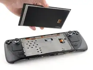
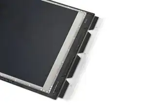
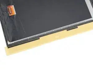
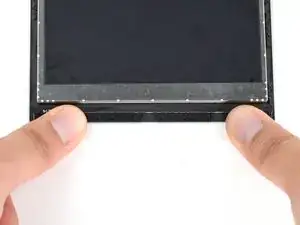
Una vez que hayas cortado el perímetro de la pantalla, levanta con cuidado el borde derecho, abriéndolo como un libro.
-
Retira la pantalla.
-
-
-
Revisa el nuevo adhesivo de la pantalla y haz coincidir cada tira con su respectivo lado de la pantalla.
-
-
-
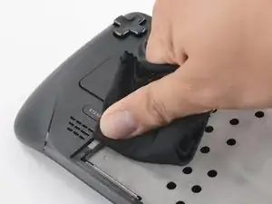
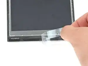
Elimina los trozos grandes de adhesivo con el extremo plano de un spudger o una herramienta de apertura de plástico.
-
-
-
Utiliza removedor de adhesivo o alcohol isopropílico (>90%) para eliminar cualquier residuo restante. Limpia en una dirección con un paño sin pelusa o un filtro de café hasta que desaparezcan todos los residuos de adhesivo.
-
Deja que el alcohol isopropílico sobrante se evapore por completo antes de volver a utilizarlo.
-
-
-
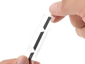
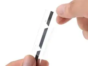
Una vez que tengas una buena idea de dónde va la tira adhesiva, despega y desecha el revestimiento, dejando al descubierto el adhesivo que hay debajo.
-
-
-
Coloca el adhesivo sobre la superficie y presiona firmemente con los dedos para fijarlo.
-
Repita los dos pasos anteriores para las otras tres tiras adhesivas del expositor.
-
-
-
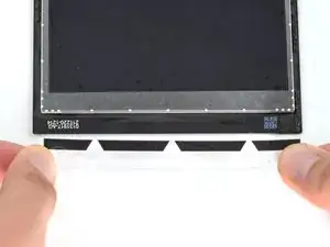
Despega y desecha los revestimientos de plástico restantes en las cuatro tiras, dejando al descubierto el adhesivo que hay debajo.
-
Repite la operación con las cuatro tiras adhesivas de la pantalla, teniendo cuidado de no tocar los adhesivos expuestos.
-
-
-
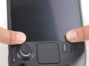
Coloca la nueva pantalla en su lugar en el marco intermedio y presiona firmemente a lo largo de los bordes durante 20-30 segundos para asegurar una buena unión adhesiva.
-


***Para volver a montar el dispositivo, sigue estas instrucciones en orden inverso.
Lleva tus residuos electrónicos a un centro de reciclaje certificado.
¿La reparación no ha ido como estaba previsto? Intenta con algunas soluciones básicas de problemas, o pide ayuda a nuestra Comunidad de respuestas de Steam Deck.

8 comentarios
Attempted this tonight after smashing the screen on my deck. Easy to follow and worked flawlessly first time. Thank you
On peut mettre un autre ecran OLED ou autre ?
This guide is gold standard. Not once did I think “why didn’t they mention this?”