Introducción
Utiliza esta guía para reemplazar la placa de entrada de CC MagSafe.
-
-
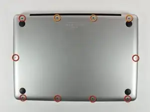
Retira los siguientes 10 tornillos que sujetan la tapa inferior del MacBook Pro 13 "Unibody:
-
Siete tornillos Phillips de 3 mm.
-
Tres tornillos Phillips de 13,5 mm.
-
-
-
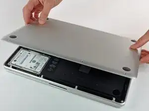
Levanta ligeramente la tapa inferior y empuja hacia la parte posterior para liberarlo de las pestañas que lo sujetan
-
-
-
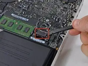
Utilice el extremo plano de un spudger para levantar el conector de la batería hacia arriba fuera de su toma en la placa lógica.
-
-
-
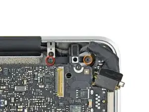
Retira los siguientes tres tornillos:
-
Un tornillo Torx T6 de 7 mm
-
Dos tornillos Torx T6 de 5,4 mm
-
-
-
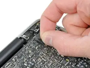
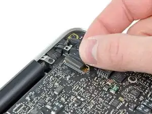
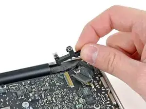
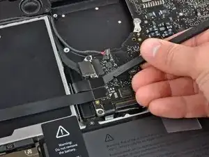
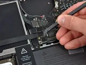
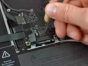
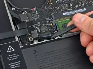
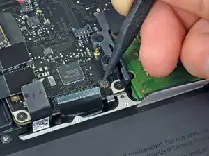
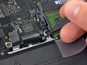
Toma la lengüeta de plástico asegurada al candado del cable de datos de la pantalla y gírala hacia el lado de entrada de CC de la computadora.
-
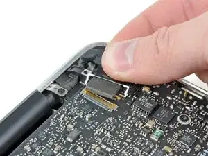
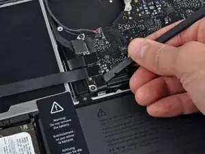
Tira con cuidado del conector del cable de datos de la pantalla paralelo a la placa.
-
-
-
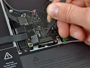
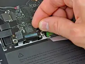
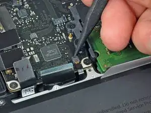
Retira los dos tornillos siguientes que sujetan el soporte del cable de datos de la pantalla a la carcasa superior:
-
Un Phillips de 8,6 mm
-
Un Phillips de 5,6 mm
-
Levanta el soporte del cable de datos de la pantalla para sacarlo de la carcasa superior.
-
-
-
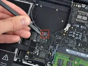
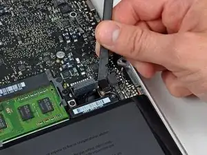
Usa el extremo plano de un spudger para levantar el subwoofer y el conector del altavoz derecho de la placa lógica.
-
-
-
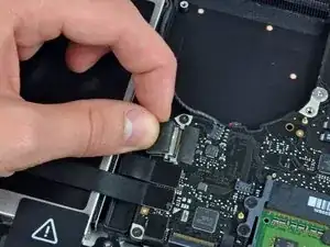
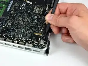
Tira del conector del cable de la cámara hacia la unidad óptica para desconectarlo de la placa lógica.
-
-
-
Usa el extremo plano de un spudger para levantar la unidad óptica, el disco duro y los conectores del cable del trackpad de la placa lógica.
-
-
-
Usa la uña o la punta de un spudger para levantar la solapa de retención del cable en el zócalo ZIF para el cable plano del teclado.
-
Usa tu spudger para deslizar el cable plano del teclado fuera de su zócalo.
-
-
-
Despega la pequeña tira de cinta negra del conector del cable plano de la retroiluminación del teclado.
-
-
-
Usa la punta de un spudger para levantar la solapa de retención del cable en el zócalo ZIF para el cable plano de la retroiluminación del teclado.
-
Usa tu spudger para deslizar el cable plano de luz de fondo del teclado fuera de su zócalo.
-
-
-
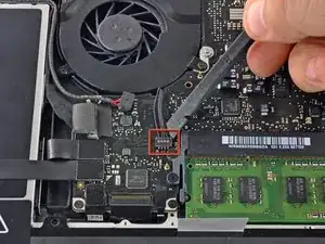
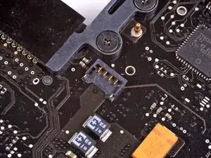
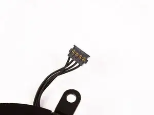
Usa el extremo plano de un spudger para levantar el conector del cable del indicador de batería de la placa lógica.
-
-
-
Usa la punta de un spudger para quitar el micrófono del adhesivo que lo une a la carcasa superior.
-
-
-
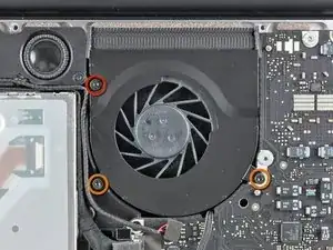
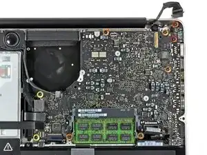
Retire los siguientes tornillos:
-
Dos tornillos Torx T6 de 7 mm de la placa de entrada de CC
-
Cinco tornillos Torx T6 de 3,3 mm
-
Dos tornillos Torx T6 de 4 mm
-
-
-
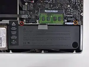
Retira los siguientes tornillos de tres puntas que sujetan la batería a la carcasa superior:
-
Un tornillo de tres puntas de 5,5 mm
-
Un tornillo de tres puntas de 13,5 mm
-
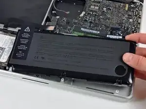
Saca la batería de la carcasa superior.
-
-
-
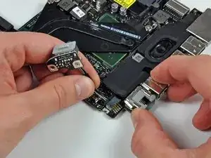
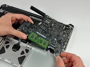
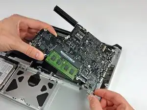
Levanta la placa lógica desde su borde izquierdo y levántala hasta que los puertos despejen el costado de la carcasa superior.
-
Separa la placa lógica del costado de la carcasa superior y retírala, teniendo cuidado con la placa de entrada de CC que puede quedar atrapada.
-

Para volver a ensamblar tu dispositivo, sigue las instrucciones en orden inverso.

4 comentarios
The Tri-wing Y1screwdriver suggested for this procedure is too big for the removal of the battery screws. I completed replacing the DC in board without removing the battery.
rkterao -
I have just tested several of those drivers from our shelf in 3 different MacBooks we have here with tri-wing type screws, and they are all a perfect fit. I have sent you an email to try and find out why your driver did not fit, you may have a mid 2009 model with pentalobular screws instead?
Thanks! Guide was wonderful! I wish there had been a bit more information about the proper routing of the dc-in cable as the first time I put it back together I accidentally routed the cable on the outside of the mother board riser which made it impossible to seat the display cable hold down clamp properly. I had to re-remove the main board in order to get the dc-in cable on the other side of the riser. Not a biggie, but a note on that step would be helpful. Thanks again!!
So I switched it out, but in the process ripped the battery indicator cable connector, and now the wifi doesn’t work either… it’s super slow to start up. Any suggestions for fixes?
Compare the short screws carefully before reinstalling them. The shouldered screws go in the holes on the front edge.
David Kilbridge -
Before I started removing any screws I took a piece of paper and drew the bottom of the laptop and put a piece of double-sided tape in the spot where each screw goes. That way when I took out the screws, I could put them on the tape so I knew exactly which screw went in which spot. I did the same thing for dismantling the inside on another sheet of paper, then a third sheet for the screen after getting the front glass off.
mastover -
I use a similar technique: I print out the iFixit manual for the job, and Scotch-tape down the screws/brackets/cables I remove at each step next to the component descriptions. That way, when I'm reassembling, the bits are taped right next to the photo of where they came from.
adlerpe -
That's exactly what I do for all my repairs! It's the best way to keep track of all of the parts ' original location and to make sure that you don't miss any parts during reassembly.
joyitsjennie -
Great idea and one I use often
Thomas Overstreet -
Excellent idea! Thanks for sharing it here.
Laura Sharkey -
I used a 00 that fit but the screws were very tight so I used a tiny paintbrush with some wd40 on it and put it around the edges of the screws. Worked like a charm
valentinedhdh -
I use a magnetic mat and place the screws in order on that :)
Cary B -