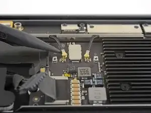
Introducción

Utiliza esta guía para reemplazar la placa lógica de una MacBook Air 2019

Ten en cuenta que el Touch ID no funcionará después de reemplazar la tarjeta lógica. El sensor Touch ID original del MacBook se empareja de forma exclusiva con el chip T2 de la placa lógica de fábrica, y sin el proceso de calibración patentado de Apple, ni siquiera una placa lógica de repuesto genuina de otro MacBook Air funcionará.

Si reemplazas la tarjeta lógica, deberás instalar un sensor Touch ID emparejado para conservar la funcionalidad del Touch ID.

  1. 4a1VSQBgdQXAZah2
    • Antes de iniciar este procedimiento, debes desactivar la función de arranque automático de tu Mac. El arranque automático se enciende en tu Mac cuando abres la tapa y puede activarse accidentalmente durante el desmontaje. Utiliza esta guía para desactivar el arranque automático.

    • Si tu MacBook está ejecutando Big Sur v11.1 o posterior, puede que no funcione la desactivación del arranque automático. Puedes proceder normalmente, pero asegúrate de desconectar la batería en cuanto estés dentro.

    • Apaga completamente y desenchufa tu MacBook Air antes de empezar. Cierra la pantalla y pon toda la portátil boca abajo.

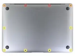
    • Usa un destornillador P5 Pentalobe para quitar los siguientes seis tornillos :

    • Dos tornillos de 7.9 mm

    • Dos tornillos de 7.1 mm

    • Seis tornillos de 2.6 mm

    If the first thing you do is disconnect the battery, is it really an issue if you don’t (or can’t) disable auto-boot?

    maccentric -

    I agree, why disable Auto-Boot when the lid is closed and the battery is disconnected immediately? – I've never had an issue since 2016 when the feature was introduced.

    stevebsiegel -

    On my machine, the longest two screws were in the corners, while the other two long screws were in the middle. Perhaps previous service in the past had them replaced into the wrong place? In any case, the longest screws do seem to fit in either place. I guess 0.8mm is not very much of a difference. Seems like poor design if they could have used one size of screw.

    johann beda -

  2. 4Kra6VLGEa3eGmd6
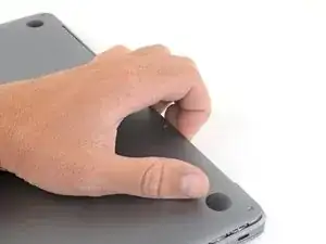
    • Pon tus dedos entre la pantalla y la caja inferior y tira hacia arriba para sacar la caja inferior de la computadora.

    • Remueve la caja inferior.

    Das geht etwas schwer, da das Unterteil mittig noch von 2 Druckverschlüssen gehalten wird.

    facebook -

  3. xVJrmDjjKX3L1VEp
    • Quita la cinta que cubre el conector de la batería lo suficiente como para revelar el conector que hay debajo.

  4. NZT3TL4hoGyeLE6L
    NZT3TL4hoGyeLE6L
    XZ2jGZmJoO1c5OHn
    • Utiliza un spudger para deslizar el conector de la batería en paralelo a la placa lógica y sacarlo de su zócalo en la placa lógica.

    Before the battery can be fully disconnected, the battery disconnect button needs to be held down. There is a gold button just above the battery socket, along with a small LED much like the 12” machines. Once this has been held down and the LED has switched off it is safe to remove the battery.

    Aaron Dalziel -

    This seems like an important step?

    maccentric -

    Also, seems like this should be done after the battery is disconnected, not before? Otherwise, wouldn’t the battery re-charge it?

    maccentric -

    What if the white LED dosent light up after pressing the yellow button again?

    Iron05 -

    I just performed this repair on my late 2018 mac air. I did click the gold button but saw no LED illuminated or otherwise. Question- after reassembly does the button get pressed again to connect the battery? Please clarify if this button is to be pressed and if it needs pressing again after the repair.

    All said - I pressed again after the battery connector clicked, assembled the back and all worked perfectly. The original issue was one dead port (no charge, no communication). The battery charge lightening bold icon was acting funny too. Genuis bar guy in Naperville said it was likely a logic board too. But it was not. The port was apparently confusing the logic board with regards to the charge function. Thanks Adam for saving me $440 and sending my computer back to Apple. I am 71 yrs young - who says an old dog can’t learn new tricks with good training!!

    William Lane -

    I didn't see Aaron's comment before completing the battery replacement. Afterwards, the computer would not turn on despite multiple SMC reset procedures. Upon double-checking the comments I see the importance of pressing the gold button. I pressed the gold button before disconnecting the new battery, then pressed it again after reconnecting for good measure. Computer booted!

    It would be good of iFixit to add this important step as most people probably don't open up every single comment on (seemingly) simple steps.

    Corey Matsumoto -

    Seconding Corey's comment. If paid more attention to the comment section, I would have avoided 15-30 minutes of panic. (BTW I did not notice any LED, but the golden button was easy to find).

    Lorenzo Sorbo -

  5. mCpNcwDmVvCIexvU
    mCpNcwDmVvCIexvU
    WCiJUh1bJboPNur2
    • Usa un destornillador Torx T3 para quitar los dos tornillos de 1.4 mm que aseguran el soporte del conector del trackpad.

    • Remueve el soporte del conector del panel táctil.

    My machine used T4 screws

    johann beda -

    Me too! I tried with T3 and it wasn’t working.

    Rose Alshuaibi -

  6. Sw6VN6VuYRYAnW2T
    Sw6VN6VuYRYAnW2T
    iGLvdxo4pDlVZOh6
    • Utiliza el extremo plano de un spudger para sacar el conector del cable del trackpad de su zócalo.

  7. 2ANOeBCRlLS1Elpu
    2ANOeBCRlLS1Elpu
    gVBNK32AwYwuWQFx
    hRm4xZQXbIkkT4O5
    • Si el altavoz izquierdo ya está desconectado, omite este paso.

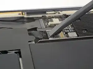
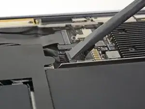
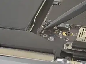
    • Desliza la punta de un spudger debajo del cable del altavoz y haz una palanca hacia arriba para desconectar el altavoz.

    • Con el conector desconectado, desliza la punta plana de un spudger bajo el cable para separar el adhesivo que asegura el cable a la placa lógica.

    I think step 15 was a mistake because it’s a repeat of step 10.

    Ryan R -

    Yeah, the speaker is already removed at this point.

    Jason _ -

  8. IHRbrlPXF2JApiqk
    IHRbrlPXF2JApiqk
    LyZ1foqy1wvBlOiv
    • Usa un destornillador T3 Torx para quitar los dos tornillos de 1.3 mm que aseguran el soporte del conector del puerto USB-C.

    • Remueve el soporte del conector de USB-C.

  9. M3RvYGtmREQuaLZ2
    M3RvYGtmREQuaLZ2
    B6AMphVrIvwKpisH
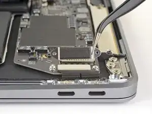
    • Utiliza el extremo plano de un spudger para sacar el conector del cable USB-C de su zócalo en la placa lógica.

  10. BjgmhIFsgtdRtuUi
    BjgmhIFsgtdRtuUi
    hgUoCSOomRaZZNMa
    XNTm2JBIuDLHFUKi
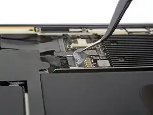
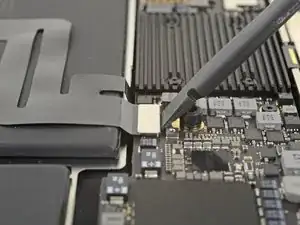
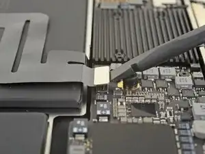
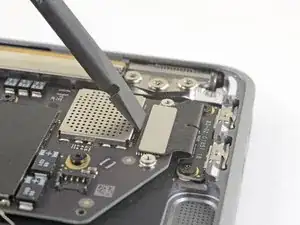
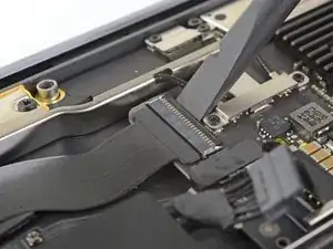
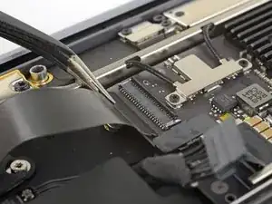
    • Utiliza un spudger para levantar la pequeña pestaña de cierre del conector ZIF del cable de la placa de sonido.

    • Desliza el cable de la placa de sonido del conector ZIF.

  11. RK65AOeFDCjfyyWv
    • Quita la cinta negra que cubre el conector del cable del ventilador.

  12. EvCAoAoChgdZSUpP
    EvCAoAoChgdZSUpP
    VORkbyxUw5mQoLXP
    EBqFtxhhx5MFDscb
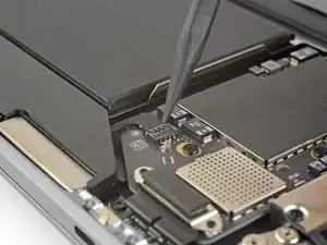
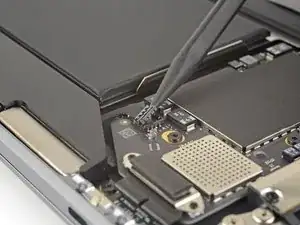
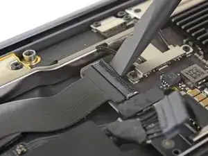
    • Utiliza la punta de un spudger para levantar la tapa de cierre del conector ZIF del cable del ventilador.

    • Desliza el cable del ventilador fuera del conector ZIF

  13. tXgZY3PV2kPaADlE
    tXgZY3PV2kPaADlE
    WAgCyw6YIrvC3RQH
    • Usa un destornillador Torx T3 para quitar los dos tornillos de 1.4 mm que aseguran el soporte del cable de la antena.

    • Remueve el soporte del cable de antena.

    These are T4 screws

    Richard Arnett -

    The MBA I just finished with were T3. I'm fairly confident with my tools as I recently updated/upgraded nearly my entire set with WiHa. I should also mention the many tools acquired from iFixit over the years have all been were exceptional lasting years. There's no doubt iFixit would have been my source but a close friend went to work for WiHa. His discount(s) & being motivated to help him was a major impact. For anyone not having such an advantage IMHO tools from iFixit are one of the best values anywhere. Let's not forget; buying from iFixit will also help to push "Right to Repair" forward. Here in Minnesota Right to repair ALMOST PASSED. Many believe it will become law during the next session! I can't tell you how proud this would make me. I would obtain as many service manuals as possible and post them all online!!! What a great dream...

    admin -

  14. SIwpML6D2V1THnvW
    SIwpML6D2V1THnvW
    HSbt4VrCJOZJWJeX
    vMkn5IqQ1LgQrMRK
    • Inserta la punta de un spudger bajo uno de los cables de la antena cerca del conector. Haz una palanca hacia arriba para desconectar el cable.

    • Repite con el otro cable de la antena.

  15. JwduCSLFH2CcraAQ
    JwduCSLFH2CcraAQ
    kTylWJvDOGiAPbQS
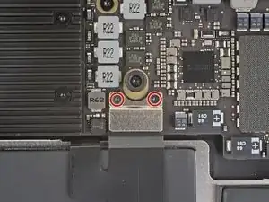
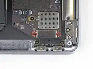
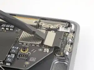
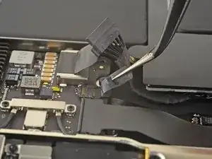
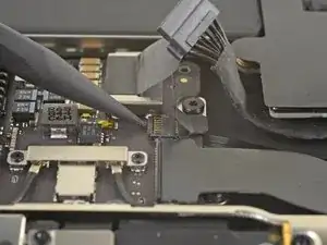
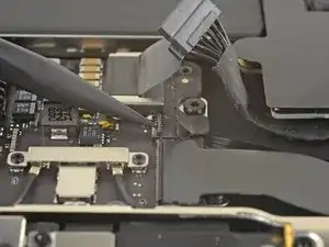
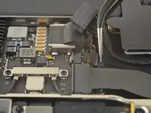
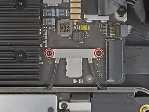
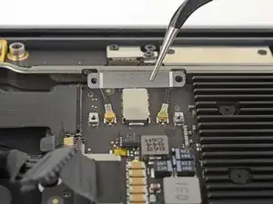
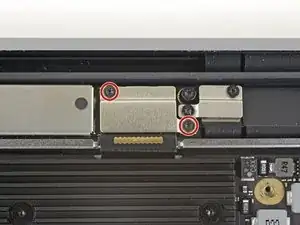
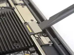
    • Usa un destornillador Torx T3 para quitar los dos tornillos de 1.5 mm que aseguran el soporte del conector del cable de la pantalla.

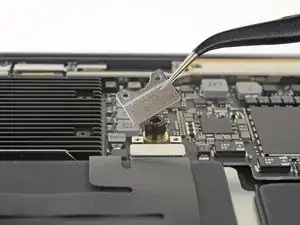
    • Remueve el soporte del conector del cable de pantalla.

  16. cELhRfbeZrcbMPps
    cELhRfbeZrcbMPps
    kHkPDOnxWduTqHLa
    • Usa el extremo plano de un spudger para levantar el conector del cable de la pantalla.

    How do I reconnect display connector??

    Kris Queck -

    Just align the plug section of the display flex with the socket on the logic board and gently press it in until it locks in place. Do not force it but just ensure it’s correctly aligned before pushing it into the socket.

    Peter Newman -

    Pro tip: You can remove the two T5 screws on the LCD connector side (located to the right of the display connector and to the left of the heat shield). From there, tilt the whole skinny LCD board towards the logic board connector and gently pinch the connector in to the socket. Before laying the skinny board back down, screw in the shield from Step 15 so it doesn’t pop out of the socket again.

    jason4 -

  17. 6TXbngaNJybXtDKP
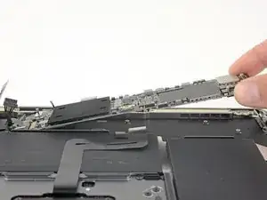
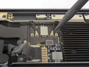
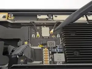
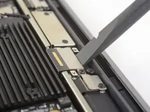
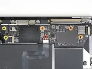
    • Usa un destornillador T5 Torx para remover los siguientes tornillos:

    • Un tornillo de 5.5 mm

    • Tres tornillos de 2.6 mm

    • Dos tornillos de 1.9 mm

    These are T5 Torx driver screws

    Richard Arnett -

    Need torx 5 AND torx 4 driver here ;)

    Marcel Popp -

    During re-assembly be soft when screwing in the logic board because those antenna plugs in Step 14 are quite awkward to pin back into their sockets and there is little leeway in the cables; to make this task a little easier in Step 14, secure the logic board loosely right up against the near outside edge; after re-connecting all the cables in Steps 16-9, return to Step 17 to firm up the logic board screws.

    Andrew Gordon -

    This tip was a huge help, hate these cables lol

    Konrad Anderson -

    The 5.5 mm screw goes into a hexagon standoff which may come off with the logic board being sanswiched beteen the 5.5 mm screw screw and the standoff like happened to me. Just something to be aware of. It also has a black rubber bumper over the screw which was not mentioned at all. It pulls straight off to give access to the screw.

    Peter Newman -

    On my board I needed to use T6 for all the screws except the rubber bumper for which I used a T7. I have a full set of small Torx drivers and tried for the best fit.

    jeffyouell -

    T5 fit best is all the screws on my machine

    johann beda -

  18. eHXdqWRQTLhS4rxV
    • Remueve la placa lógica.

Conclusión

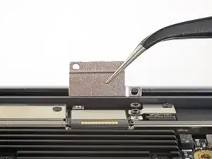
Compara la nueva pieza de repuesto con la original. Es posible que tengas que transferir los componentes restantes o retirar los respaldos adhesivos de la nueva pieza antes de instalarla.

Para volver a montar el dispositivo, sigue los pasos anteriores en orden inverso.

Lleva tus desechos electrónicos a un centro de reciclaje certificado.

¿La reparación no salió como planeaste? Echa un vistazo a nuestra comunidad de respuestas para ayuda en la resolución de problemas.

Adam O'Camb

Miembro Desde 11/04/15

179525 Reputación

Un comentario

Consulta , para este modelo el cambio de pasta disipadora es diferente a modelos anteriores, es factible colocarle una HY510 HEATSINK?

A lo que voy es que yo desmonte un equipo, y lo revise y veo que la pasta esta medio seca.

Arturo Lugo -