Introducción
Herramientas
-
-
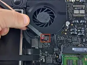
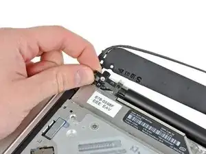
Retira el acolchado suave que puede estar en la parte superior y tira suavemente del conector para sacarlo de su zócalo en la placa lógica.
-
-
-
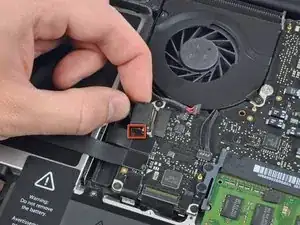
Tira del conector del cable de la cámara hacia la unidad óptica para desconectarlo de la placa lógica.
-
-
-
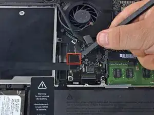
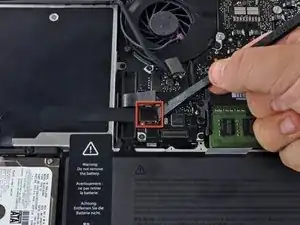
Usa el extremo plano de un spudger para sacar el conector de la unidad óptica de la placa lógica.
-
-
-
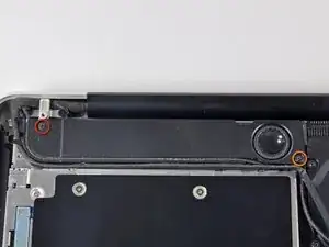
Remueve los siguientes tornillos que aseguran el altavoz a la tapa superior
-
Un tornillo 3.8 mm Philips
-
Un tornillo Philips 5 mm
-
-
-
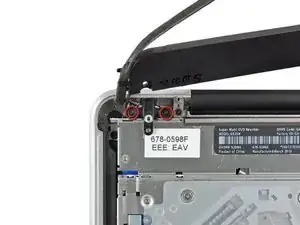
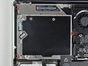
Remueve los dos tornillos Philips de 10 mm que aseguran el soporte del cable de la cámara a la tapa superior.
-
Levanta el soporte del cable de la cámara fuera de la tapa superior.
-
-
-
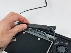
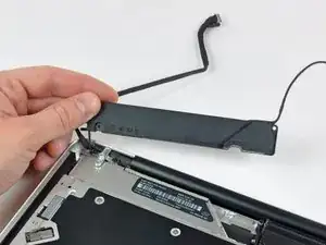
Remueve los tres tornillos Phillips de 2.5 mm que aseguran la unidad óptica a la tapa superior.
-
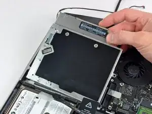
Levanta la unidad óptica desde la esquina derecha y retírala de la computadora.
-
Para volver a ensamblar el dispositivo, sigue las instrucciones en orden inverso.

Un comentario
Bonsoir. Le tuto est très clair, mais je voudrais savoir s’il est applicable sur la version 15” du MBP 10. Amicalement, Marc.
It is not necessary to remove the camera cable connector (step 5) or the camera cable connector (step 10). Simply push the camera cable gently aside to remove one of the three screws securing the optical drive (step 11). Gently wiggle the optical drive from under the camera cable connector and go to step 12. Less chance of ruining your motherboard!
tomhart -
Absolutely. Leave it alone, you don’t need to run the risks of removing this cable, I did the replacement fine without it
Steven Taylor -
It does indeed come out of the connector, but the picture makes it hard to see how; the connector it goes into sits on top of the board—however, I, too, ripped mine off the board trying to remove it; I only got it out of the clip after I tore it off. SIMPLY DONT; it's unnecessary. I plan to solder it back if one of my Robotics club friends lets me borrow a soldering iron.
Rachel -
Alors je déconseille très fortement de toucher ce connecteur, il est extrêmement fragile. De plus, cela n’a pas d’incidence sur la suite des opérations
Laskoni -
The author needs to go back through this guide and correct lots of order mistakes. The fan was removed in steps 3-5 yet it’s still being shown installed in steps 19-22.
plink53 -