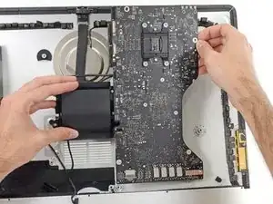
Introducción

Guía de prerequisito únicamente.

  1. bpUJduIptxtCQTrJ
    bpUJduIptxtCQTrJ
    NY3U2MjTCPHSNjfv
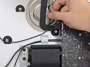
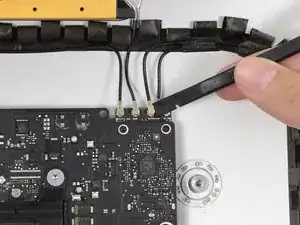
    • Empuja en cada lado del conector del cable del altavoz izquierdo con la punta de un spudger para que lentamente "camine" fuera de su zócalo.

    As noted in the right speaker cable section, the two corners of the connector are latches that need to be pushed toward the center of the connector to release. This is easily done with the pointed end of the spudger. Once the two corner latches are released, the connector comes apart easily.

    Fred Heineman -

  2. nIBOyJbEX5Sl4Or2
    nIBOyJbEX5Sl4Or2
    pAPeO3l2vihSiYDM
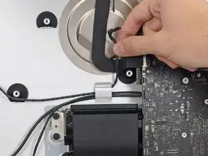
    • Desvía el cable del altavoz izquierdo tirando de él hacia arriba fuera del clip de retención en el fondo de la carcasa posterior.

  3. aPduYkOrm1ijEuIm
    aPduYkOrm1ijEuIm
    J3l5W2gyvQbjlT4W
    nPMIkqvYZHIUCEXb
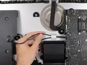
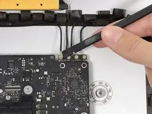
    • De una forma similar al paso anterior, desvía los cables SATA de alimentación y datos fuera del clip de retención.

  4. Oi1uPFeAgU4d4B1V
    Oi1uPFeAgU4d4B1V
    UQYT31FILKH2XlFo
    deVi3sgpTG6ko3ev
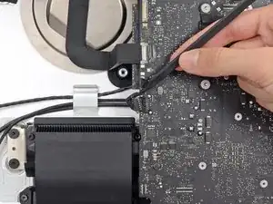
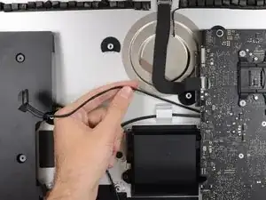
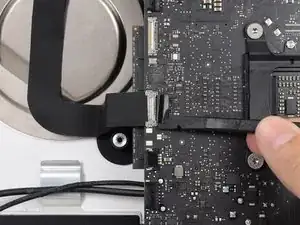
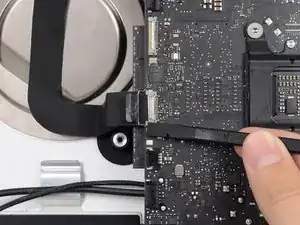
    • Usa la punta plana de un spudger para voltear hacia arriba el soporte metálico de retención en el conector del cable de la cámara iSight.

    • Tira el cable de la cámara iSight fuera de su zócalo en la placa lógica.

    • Este es un conector delicado que puede ser fácilmente dañado.

    As seen in the photo this clip clearly has a pull tab. Forget the spudger and just open the clip with the pull tab.

    airshack -

  5. ChWlT2nybGpoDtrw
    ChWlT2nybGpoDtrw
    2LQdOvIdwuPacACY
    52lBdh3y1pIxgFri
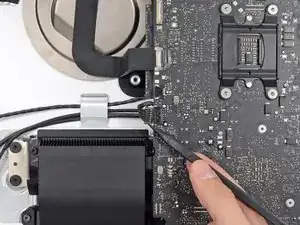
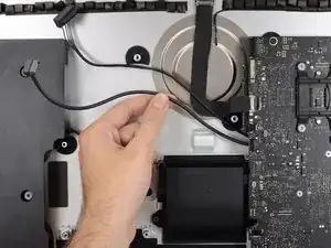
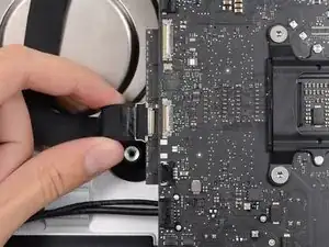
    • Usa la punta plana de un spudger para desconectar cada uno de los cuatro conectores de la antena de la tarjeta AirPort/Bluetooth.

    • Recuerda las posiciones originales de cada conector cuando reconectes los cables.

    I broke off one of the antenna connectors when I took off the antenna wires, but the new 802.11ac card is working:) I seems the way to take off the wires is lifting it up from the wire side. In hindsight I just wasn´t careful enough.

    Runar Vaernes -

    how do I check a working logic board

    Navneet Garg -

    I labeled mine with label printer labels prior to disconnection.

    airshack -

    I labeled mine with label printer labels prior to disconnection. The label/tabs made reinstalling easier as I held onto the label/tabs while pressing down on the connectors. Much easier than holding onto the physical wires.

    airshack -

    If you have a pair of angled tweezers, they work well for grabbing under the connector so that you aren’t pulling on the wire. The head of the T10 screwdriver works well for pressing them back on.

    Mitchell Scheffler -

  6. PVF2eFHOcWUlH6ov
    PVF2eFHOcWUlH6ov
    qbxXCqIthxynZ525
    tjH4h6FyAyucQGqX
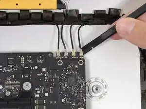
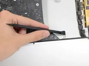
    • Usa la punta plana de un spudger para quitar el conector del cable del jack de conexión de auriculares de su zócalo en la placa lógica.

    • Empuja el cable ligeramente a la derecha.

    Unlike the rest of the connectors on the logic board, this one lifts up away from the board rather than to the side. That “Push the cable slightly to the right.” notation is after the connector is free.

    Fred Heineman -

  7. QJIoRvsnlHELAikU
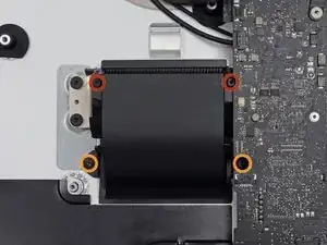
    • Remueve los siguientes tornillos que aseguran el ducto de ventilación a la carcasa posterior:

    • Dos tornillos T8 de 6.3 mm

    • Dos tornillos T8 de 4.7 mm

    Weirdly, these screws didn’t work with my T8 driver. Not with T6 or T10.

    Every other screw (to this point) has been fine. Hmm.

    Jake Lodwick -

    ??? The T8 worked fine for me. Not sure what the difference would be.

    Fred Heineman -

    Fare molta attenzione alla vite in fondo a destra, è facile (soprattutto se la punta del proprio cacciavite non è magnetizzata) che la vite si perda sotto alla Logic board. Se la punta del cacciavite non è magnetizzata consiglio o di utilizzare un magnete esterno o di utilizzare delle pinze mentre si svita la vite in modo da non incorrere in questo problema.

    Carlo Molta -

  8. vTFjxoQJVL1LjsGU
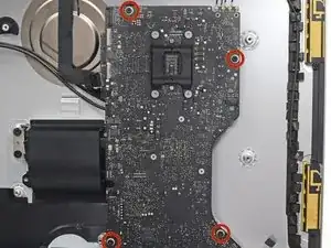
    • Remueve los cuatro tornillos T10 de 7.2 mm que aseguran la placa lógica a la carcasa posterior.

    When reinstalling the logic board, install four screws loose. Insert thumb drives into the back in all slots to ensure alignment. Once aligned, then tighten screws.

    Gary Kelch -

  9. CbhcbTbVVbCDOdVR
    CbhcbTbVVbCDOdVR
    3ZWTvdymBERwUaSS
    kWgY5CCYya3SJRcj
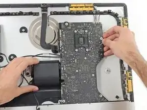
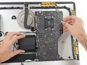
    • Inclina la parte superior de la placa lógica fuera de la carcasa posterior.

    • Levanta la placa lógica hacia arriba y fuera del iMac.

    • Ten cuidado de no enganchar la placa en alguno de los postes de tornillo que hay en la carcasa posterior.

    • La sección de E/S en el pie de la placa lógica será el desafío mayor. Se recomienda que tires con cuidado para prevenir cualquier daño.

    • Durante el reensamblaje de la placa lógica, presa atención a la posición de los conectores de E/S. Cuando la placa esté de nuevo en la carcasa, inserta un cable USB o Thunderbolt en uno de los conectores para alinearla perfectamente.

    When inserting the logic board back, pay attention of the position of the I/O connectors. When it is back in place, put a USB / Thunderbolt cable into the connectors to ensure the perfect alignment.

    Peter -

    This is fantastic advice. I used a combination of USB and display port plugs to ensure proper alignment and help keep the logic board steady while i screwed it back in. Thank you!!

    kazoodac -

    Great technique. I plugged a cable into every port before tightening logic board screws.

    airshack -

    ive gotten this far and i still have one question, i’m replacing my HDD With A SSD should i also remove the original Blade drive ? and run exclusively off the ssd, ? i wasn’t 100 on whether or not i was getting the fusion set up so i’m not in possession of a upgraded blade, so i though this was a good question id hadn’t seen asked.

    Eliasar -

Conclusión

Para reensamblar tu dispositivo, sigue estas instrucciones en orden inverso.

Sam Goldheart

Miembro Desde 19/10/12

457951 Reputación

0 comentarios