Introducción
Sigue esta guía para reemplazar un digitalizador roto o dañado en el Nintendo Switch Lite. Esta reparación no requiere remover los joysticks o botones, pero hace la reparación mucho más fácil.
El Switch Lite usa tornillos JIS, pero puedes usar un destornillador Phillips en caso de apuro. Ten mucho cuidado de no dañar los tornillos. Las puntas Phillips de iFixit están diseñadas para ser compatibles con los tornillos estilo JIS.
Nota: Esta guía es solo para el digitalizador. Si la pantalla LCD dejó de funcionar, es posible que solo debas reemplazarla, en lugar del digitalizador. Si estás reemplazando la pantalla (la pantalla LCD adjunta al digitalizador), sigue this guide.
Nota: Este procedimiento requiere que se remueva la placa protectora y el disipador de calor. La pasta térmica tendrá que ser limpiada de ambos componentes-así como del CPU-y reaplicada antes de reinstalar la placa de blindaje y el disipador de calor.
-
-
Usa un destornillador Y00 para quitar los cuatro tornillos de 6.3 mm de largo que aseguran el panel trasero.
-
-
-
Usa un destornillador JIS 000 o un Phillips 000 para remover los siguientes tornillos que sujetan el panel trasero.
-
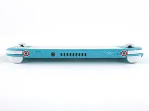
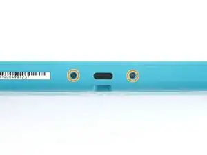
Dos tornillos de 3.6 mm en la parte superior del dispositivo.
-
Dos tornillos de 3.6 mm en la parte inferior del dispositivo.
-
-
-
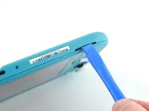
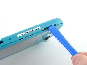
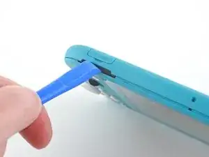
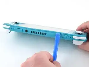
Inserta una herramienta de apertura en la rejilla del altavoz izquierdo en la parte inferior del dispositivo.
-
Gira la herramienta de apertura para liberar los clips que aseguran el panel trasero.
-
-
-
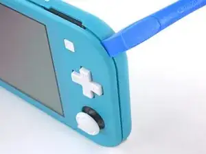
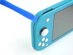
Desliza la herramienta de apertura por la esquina inferior izquierda para liberar los clips del lado izquierdo del dispositivo.
-
-
-
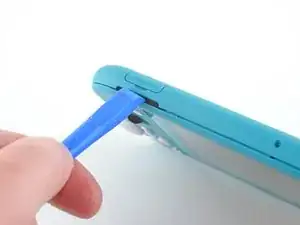
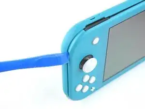
Inserta la herramienta de apertura en la rejilla del altavoz derecho en la parte inferior en el dispositivo.
-
Gira la herramienta de apertura para liberar los clips.
-
-
-
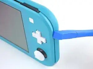
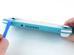
Desliza y empuja la herramienta de apertura por la esquina inferior derecha para liberar los clips del lado derecho del dispositivo.
-
-
-
Continúa deslizando y apretando la herramienta de apertura a lo largo del hueco en la parte superior del dispositivo para liberar los clips.
-
-
-
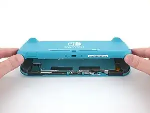
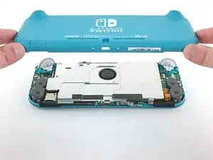
Levanta el borde inferior del panel trasero abriéndolo como un libro.
-
Remueve el panel trasero.
-
-
-
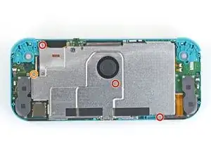
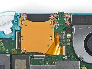
Usa un destornillador JIS 000 o un Phillips (de cruz) 000 para remover los cuatro tornillos siguientes:
-
Tres tornillos de 3.1 mm
-
Un tornillo de 4.5 mm
-
-
-
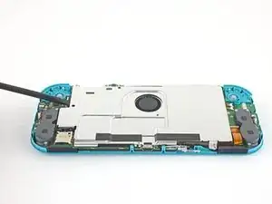
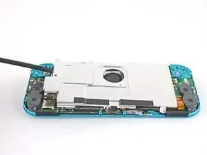
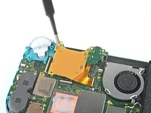
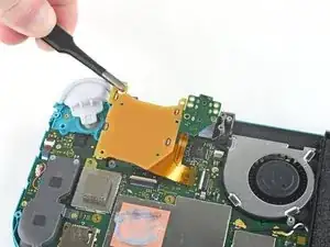
Usa un spudger o sus dedos para levantar la placa del escudo y sacarla del dispositivo.
-
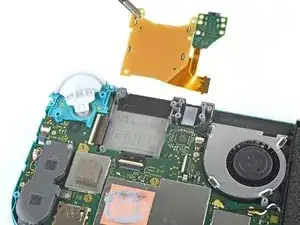
Remueve la placa de escudo.
-
-
-
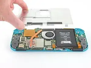
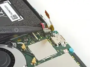
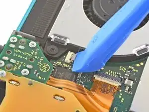
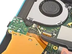
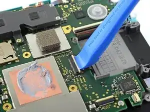
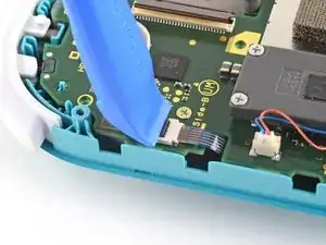
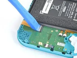
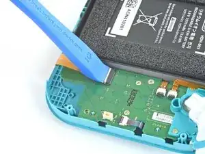
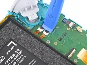
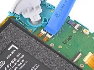
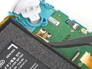
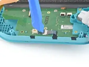
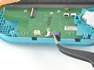
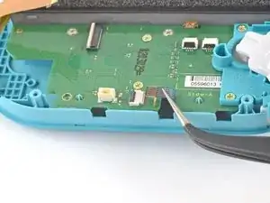
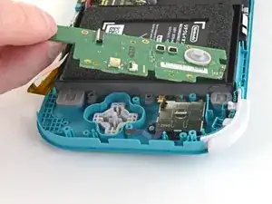
Utiliza una herramienta de apertura o tu uña para levantar la pequeña tapa de cierre con bisagra del conector ZIF del cable de interconexión de la placa madre.
-
-
-
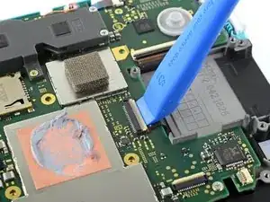
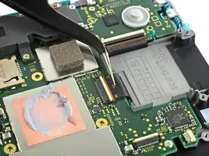
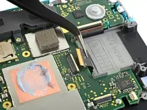
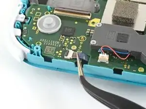
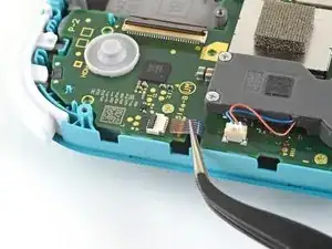
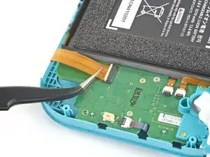
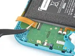
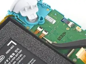
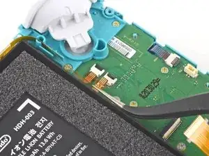
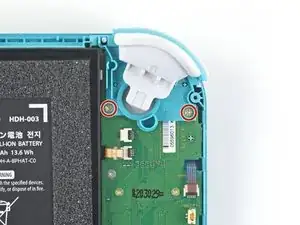
Usa la punta de un spudger para levantar el conector de la batería de su zócalo en la placa madre.
-
-
-
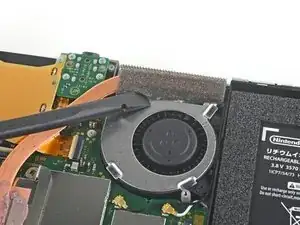
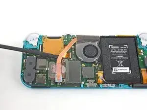
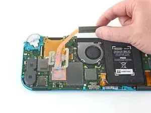
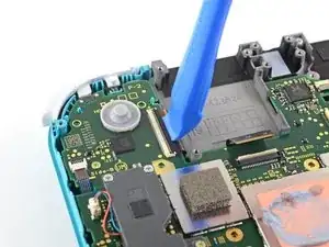
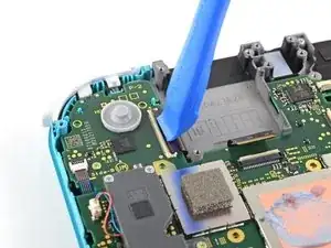
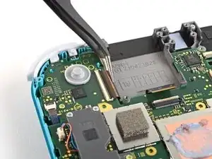
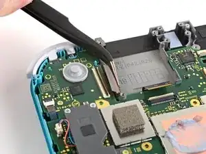
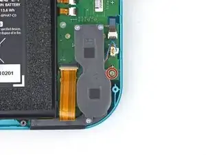
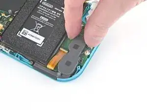
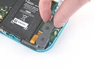
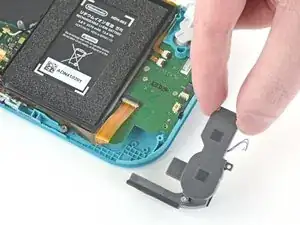
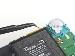
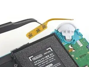
Usa el extremo plano de un spudger o tus dedos para despegar con cuidado la espuma que está adherida al ventilador.
-
-
-
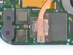
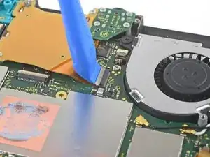
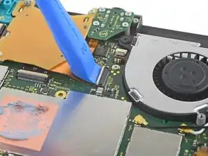
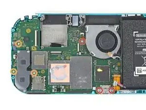
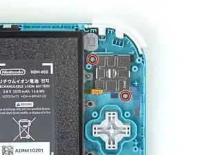
Usa un destornillador JIS o un destornillador oficial iFixit PH 000 para quitar los tres tornillos de 3 mm que aseguran el disipador de calor a la placa madre.
-
-
-
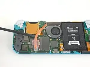
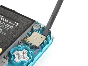
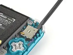
Utiliza una herramienta de apertura o tu uña para levantar la pequeña tapa de cierre con bisagras del conector ZIF del cable del lector de tarjetas de juego.
-
-
-
Utiliza un destornillador JIS 000 o un destornillador oficial iFixit PH 000 para retirar los siete tornillos de 3,1 mm que sujetan el lector de tarjetas de juego y la toma de auriculares.
-
-
-
Utiliza unas pinzas o tus dedos para levantar con cuidado el lector de tarjetas de juego y maniobrar hacia la izquierda para sacar el cable de su conector.
-
Retira el lector de tarjetas de juego y la toma de los auriculares.
-
-
-
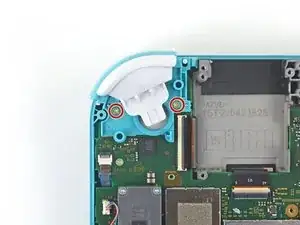
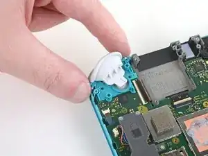
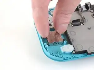
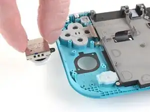
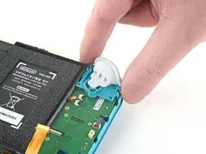
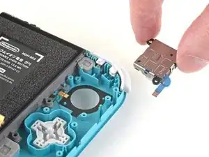
Utiliza un destornillador JIS 000 o un destornillador iFixit PH 000 oficial para quitar los dos tornillos de 4,5 mm que sujetan el conjunto del botón disparador derecho a la placa base.
-
-
-
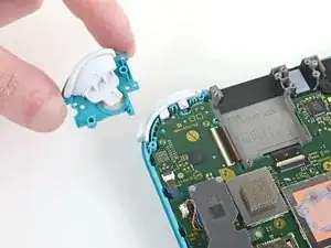
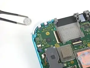
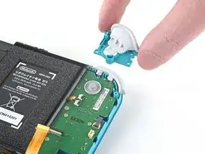
Usa un par de pinzas o tus dedos para quitar la almohadilla de goma del conjunto del botón del gatillo derecho si no quedó adherido al conjunto del botón.
-
-
-
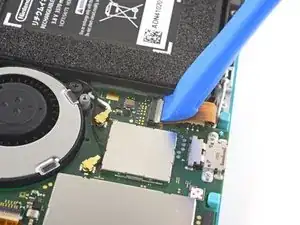
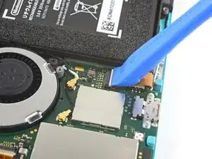
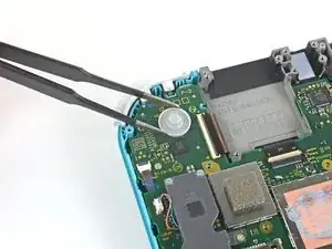
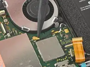
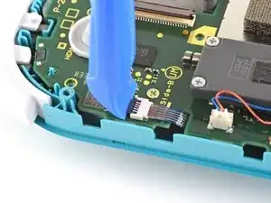
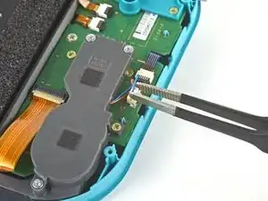
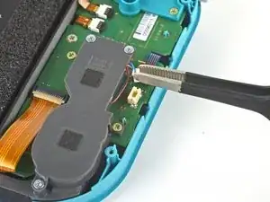
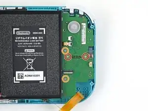
Usa la punta de un spudger para sacar el cable negro de la antena de su zócalo en la placa base.
-
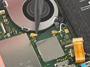
Repite el mismo proceso para el cable de antena blanco.
-
-
-
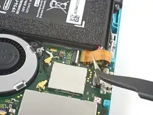
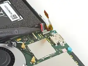
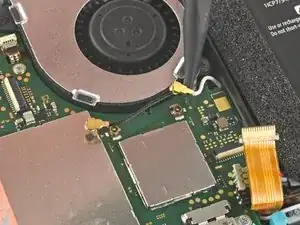
Usa una herramienta de apertura o la uña para levantar la pequeña solapa de bloqueo con bisagras en el conector ZIF del cable del ventilador.
-
-
-
Usa una herramienta de apertura o tu uña para levantar la pequeña solapa de bloqueo con bisagras en el conector ZIF del cable de pantalla.
-
-
-
Usa un par de pinzas para deslizar el cable de la pantalla fuera de su conector en la placa base.
-
-
-
Utiliza una herramienta de apertura o la uña para levantar la pequeña solapa de bloqueo con bisagras del conector ZIF del cable del digitalizador.
-
-
-
Usa un par de pinzas para deslizar el cable del digitalizador fuera de su conector en la placa base.
-
-
-
Usa una herramienta de apertura o la uña para levantar la pequeña solapa de bloqueo con bisagras en el conector ZIF del cable del joystick derecho.
-
-
-
Usa un par de pinzas para deslizar el cable del joystick derecho fuera de su conector en la placa base.
-
-
-
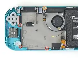
Usa un controlador JIS 000 o un controlador oficial iFixit PH 000 para quitar los siguientes seis tornillos que sujetan la placa base:
-
Tres tornillos de 3,1 mm
-
Tres tornillos de 4,5 mm
-
-
-
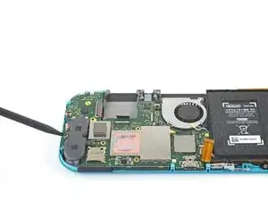
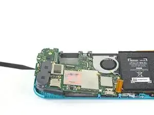
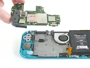
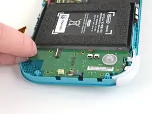
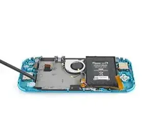
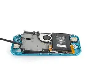
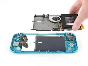
Inserta un spudger en el espacio entre el marco y la placa base y levanta la placa base para sacarla de su hueco.
-
Retira el conjunto de la placa base.
-
-
-
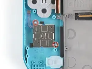
Utiliza un destornillador JIS 000 o un destornillador iFixit PH 000 oficial para quitar los dos tornillos de 3,5 mm que sujetan el joystick.
-
-
-
Usa un par de pinzas o tus dedos para sacar el cable del altavoz izquierdo directamente de su zócalo en la placa hija.
-
-
-
Utiliza una herramienta JIS 000 o una oficial iFixit PH 000 para quitar el tornillo de 4,5 mm que sujeta el módulo del altavoz izquierdo.
-
-
-
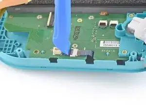
Utiliza una herramienta de apertura o tu uña para levantar la pequeña tapa de cierre con bisagra del conector ZIF del cable de interconexión de la placa madre.
-
-
-
Usa unas pinzas para deslizar el cable de interconexión de la placa madre fuera de su conector en la placa hija.
-
-
-
Utiliza una herramienta de apertura o su uña para levantar las pequeñas lengüetas de cierre con bisagras de los dos conectores ZIF del cable plano.
-
-
-
Usa un par de pinzas para deslizar el cable de la pantalla de la placa hija fuera de su conector en la placa madre.
-
Repite este procedimiento para el cable del botón de volumen.
-
-
-
Utiliza una herramienta de apertura o tu uña para levantar la pequeña tapa de cierre con bisagra del conector ZIF del cable del joystick izquierdo.
-
-
-
Usa un par de pinzas para sacar el cable del joystick izquierdo de su conector en la placa hija.
-
-
-
Usa una herramienta JIS 000 o una oficial iFixit PH 000 para quitar los dos tornillos de 4.5 mm que aseguran el ensamblaje del botón del gatillo izquierdo.
-
-
-
Usa una herramienta JIS 000 o una oficial iFixit PH 000 para retirar los cuatro tornillos siguientes:
-
Dos tornillos de 4.5 mm
-
Dos tornillos de 6 mm
-
-
-
Usa una herramienta JIS 000 o una oficial iFixit PH 000 para quitar los dos tornillos de 3,5 mm que aseguran el joystick izquierdo.
-
-
-
Usa el extremo plano de un spudger para levantar el joystick de su hueco.
-
Usa tus dedos para remover el joystick.
-
-
-
Usa un destornillador Phillips para remover los cuatro tornillos siguientes:
-
Tres tornillos de 2.5 mm
-
Un tornillo de 6 mm
-
-
-
Usa un spudger o tus dedos para levantar el ensamblaje de marco medio fuera de su hueco.
-
Remueve el ensamblaje del marco medio.
-
-
-
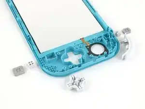
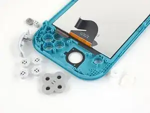
En este punto de la reparación, quita todos los botones si no lo has hecho ya, para evitar que se caigan y se pierdan.
-
-
-
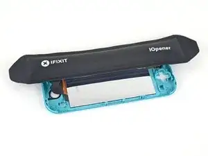
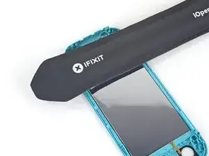
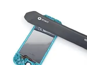
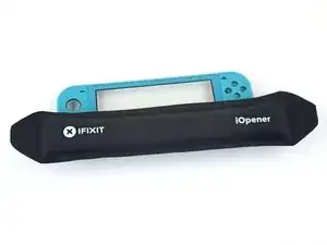
Calienta un iOpener y aplícalo en la parte posterior de la pantalla LCD a lo largo del borde superior durante 2 minutos.
-
-
-
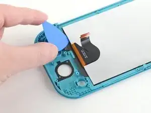
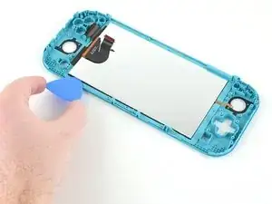
Inserta una púa de apertura entre el marco y el borde superior de la LCD para comenzar a separar los dos componentes.
-
-
-
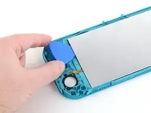
Aplica un iOpener calentado en la parte posterior de la pantalla LCD a lo largo del borde derecho durante 2 minutos.
-
-
-
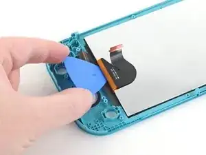
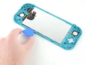
Continúa deslizando la púa de apertura alrededor del borde derecho de la pantalla LCD, cortando el adhesivo.
-
-
-
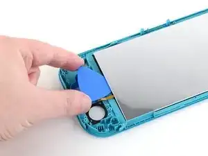
Aplica un iOpener calentado en la parte posterior de la pantalla LCD a lo largo del borde inferior durante 2 minutos.
-
-
-
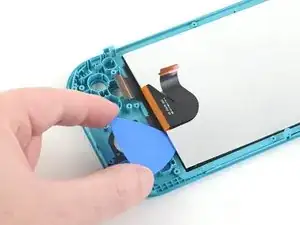
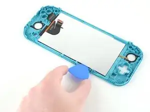
Continúa deslizando la púa de apertura a lo largo del borde inferior de la LCD para cortar el adhesivo.
-
-
-
Aplica un iOpener calentado en la parte posterior de la pantalla LCD a lo largo del borde izquierdo durante 2 minutos.
-
-
-
Continúa deslizando la púa de apertura a lo largo del borde izquierdo de la LCD para cortar el adhesivo
-
-
-
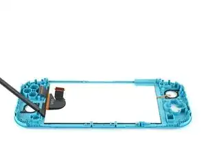
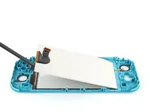
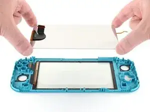
Utiliza el extremo plano de un spudger o tus dedos para levantar la LCD y sacarla del marco para quitarla.
-
-
-
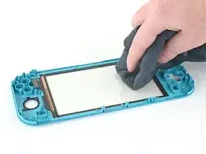
Usa el extremo plano de un spudger para raspar el adhesivo restante alrededor del perímetro del digitalizador.
-
-
-
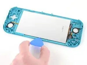
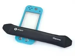
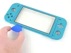
Aplicaun iOpener calentado en la parte frontal del digitalizador a lo largo del borde izquierdo durante 2 minutos.
-
-
-
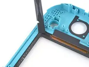
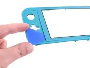
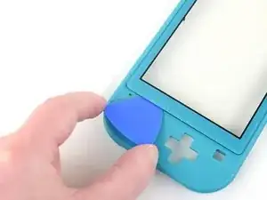
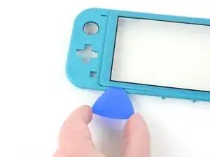
Dobla ligeramente el lado izquierdo del marco para crear un espacio entre el digitalizador y el marco.
-
Inserta una púa de apertura en el hueco.
-
-
-
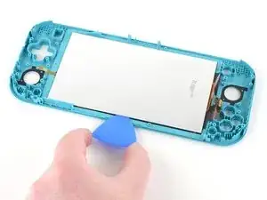
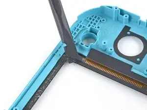
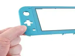
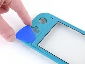
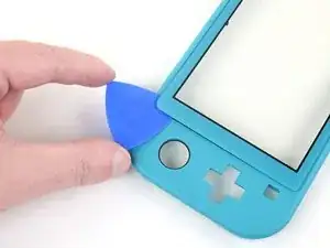
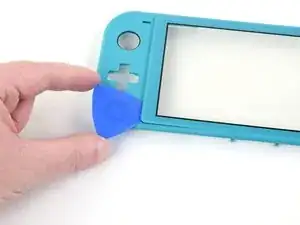
Desliza la púa de apertura a lo largo del borde izquierdo del digitalizador para cortar el adhesivo.
-
-
-
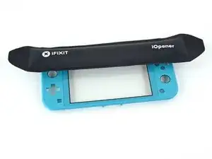
Aplica un iOpener calentado en la parte frontal del digitalizador a lo largo del borde superior durante 2 minutos.
-
-
-
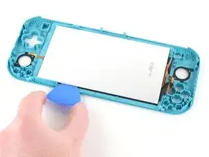
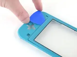
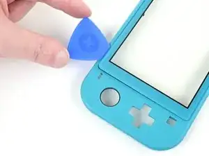
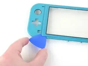
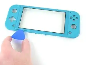
Continúa deslizando la púa de apertura alrededor del borde superior izquierdo del digitalizador para cortar el adhesivo.
-
-
-
Desliza la púa de apertura a lo largo del borde superior del digitalizador para cortar el adhesivo.
-
-
-
Aplica un iOpener calentado en la parte frontal del digitalizador a lo largo del borde inferior durante 2 minutos.
-
-
-
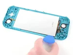
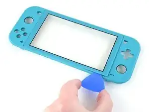
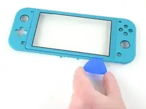
Continúa deslizando la púa de apertura alrededor del borde inferior izquierdo del digitalizador para cortar el adhesivo.
-
-
-
Desliza la púa de apertura a lo largo de borde inferior del digitalizador para cortar el adhesivo.
-
-
-
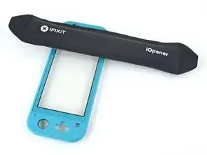
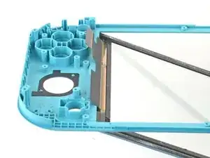
Aplica un iOpener calentado en la parte frontal del digitalizador a lo largo del borde derecho durante 2 minutos.
-
-
-
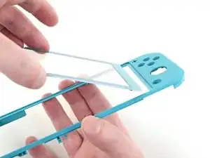
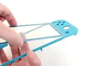
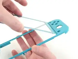
Usa tus manos para levantar lentamente el lado izquierdo del digitalizador, abriéndolo como un libro.
-


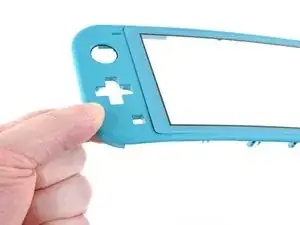
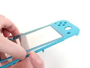

Para volver a ensamblar tu dispositivo, sigue los pasos arriba en orden inverso.
Lleva tus desechos electrónicos a un centro de reciclaje certificado.
¿La reparación no salió como planificaste? Intenta algunas soluciones para problemas básicos, o pide ayuda a nuestra http://www.ifixit.com/Answers/Device/Nin...)|comunidad de respuestas de Nintendo Switch Lite]

4 comentarios
Great guide, but quick tip when removing the screen. There are two pieces of the screen sandwiched together and when I took mine apart, these two pieces came unstuck and ruined the screen itself. The digitizer was fine, but the LCD came apart. So make sure the opening pick gets under both of these parts rather than just the reflective back.
I bought this Switch Lite with a broken LCD to repair and sell, so the screen was already blown out, but I had the same issue. The LCD was still connected to the digitizer and it actually peeled the LCD apart. As I said earlier, the LCD was already broke so it wasn’t a big issue, but I would of been fairly angry if it hadn’t of been.
it looks like it might be possible to do steps 1 - 10, then step 28, then steps 66 onwards, and reverse to reassemble, the guide isn’t clear why it would be required to do a full tear down, is there something that would make this method not work or more likely to cause further damage, if I’m just switching out the digitizer, pun intended.. :) ?
Were I to guess, I would say that the full teardown guide is meant to apply to any, and all, scenarios, regardless of any unmentioned issues that a user may have.
Another possibility is that if a user has a damaged digitizer from a drop, or other type of impact(s); then by performing a full teardown, they may discover other elements in need of repair.
All my screws got stripped any ideas on how to remove?
Almost A Mammal -
A Y0 screwdriver seemed to work better for me.
Tommy Morrill -
What type of screw driver do I use to un screw the screws and which way
Luca Capito -