Introducción

Prerequisito para remover el ensamblaje de la placa lógica (placa lógica, disipador de calor, tarjeta airport. etc.) Utilizado para guías de placa lógica y guías de caja superior.

  1. nXYZxlXybYp2WXHn
    nXYZxlXybYp2WXHn
    CH6BErvRpxNVAaBE
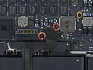
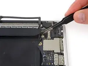
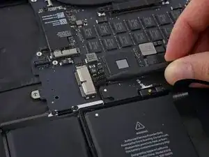
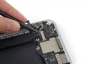
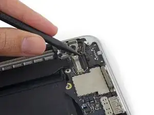
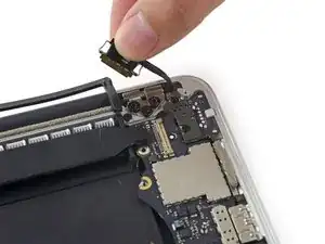
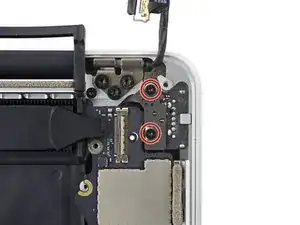
    • Remueve los dos tornillos Torx T5 de 2.2 mm que sujetan la tapa del conector de cable del panel táctil a la placa lógica.
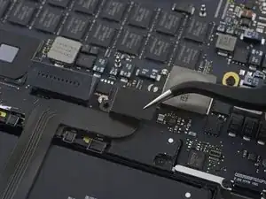
    • Remueve la tapa.

    I'm confused why it's necessary to remove the entire logic board to replace the right speaker?

    Don't you just need to remove the I/O board for the right speaker?

    Steve Rieck -

  2. bxDQI1QGgX2ock1U
    bxDQI1QGgX2ock1U
    ugAQSUqdKmkdo5jM
    ASKMc61pMrsXNOhR
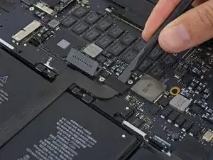
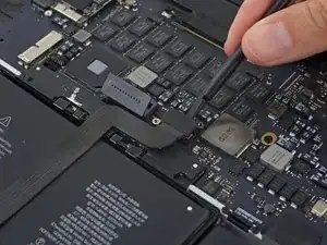
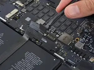
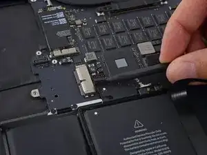
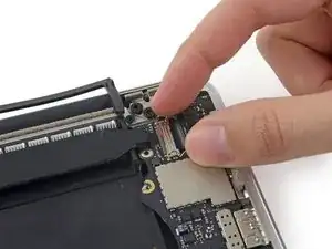
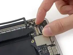
    • Utiliza el extremo plano de un spudger para desconectar el conector del cable del panel táctil de su zócalo en la placa lógica.

    • Torcer levemente el extremo plano de un spudger es la forma fácil de levantar el conector del cabler de estos tipos de zócalos.

    • Ten cuidado de solo hacer palanca contra el conector y no en el zócalo de la placa lógica.

  3. OxjrwPwrowQATefd
    • Remueve la pequeña tapa de goma del tornillo en el extremo del disipador de calor.

  4. 2BgFh3plOh2lfU2F
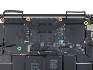
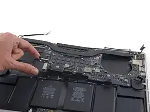
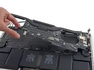
    • Remueve los siguientes seis tornillos que sujetan el ensamblaje de la placa lógica a la caja superior.

    • Un tornillo Torx T5 de 3.8 mm

    • Dos tornillos Torx T5 de 5.7 mm

    • Un tornillo Torx T5 de 5.6 mm (este es de plata y tiene una cabeza más alta que los otros)

    • Un tornillo Torx T5 de 2.6 mm

    • Un tornillo Torx T5 de 3.2 mm

    • Al volver a ensamblar, comienza con todos los seis tornillos, pero no aprietes ninguno. Mueve la placa lógica hasta que todos los tornillos estén centrados en los orificios y los puertos estén alineados con sus aberturas en el costado de la caja superior. Luego, ajusta todos los tornillos.

    Top left and right screw (red, yellow) are silver, the other ones black.

    Peter G -

    Screw with blue circle was in a slightly different position on my logic board; the gold plating surrounding it is the giveaway.

    prreitz -

    This step is really best done after all the cables are removed (Step 40).

    maccentric -

    On the other hand, when reassembling, keep the screws until this step 29

    Patrick Nance -

    The red screw above is the same one I had to remove to remove the I/O board back in step 24

    Al Moulder -

  5. bvP3EeBrBxPrx5YK
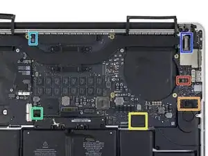
    • Los siguientes pasos detallarán la desconexión de estos seis conectores. Asegúrate de leer cada paso ya que estos conectores vienen en estilos diferentes que se desconectar de forma diferente.

    • Cable del micrófono

    • Cable del altavoz izquierdo

    • Cable de datos del teclado

    • Cable del altavoz derecho

    • Cable de luz posterior del teclado

    • Cable de datos de pantalla

    • Al volver a ensamblar, verifica que estos conectores estén conectados y completados insertados en sus zócalos.

    Save this step until you get to step 40

    I would wait until after step 39 to remove these screws. Once they are removed, the logic board jiggles around and makes disconnecting the various cables in 31-39 more difficult.

    Daniel Christie -

    Bild/Schritt 30: Bitte beide Wörter "Lüfters” durch “Lautsprechers” ersetzen

    Norbert -

    Agree with Daniel Christie. Wait until step 39.

    Patrick Nance -

  6. OkKAvgxV6J25PkZd
    OkKAvgxV6J25PkZd
    lkDLStTM6AqCKOWI
    gKLGsTErD5APuZiw
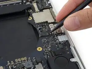
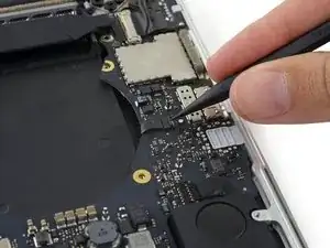
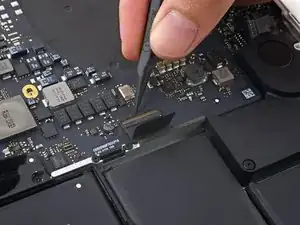
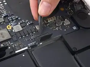
    • Usa la punta de un spudger para voltear la lengüeta de retención en el zócalo ZIF del cable de cinta del micrófono.

    • Jala y retira de su zócalo el cable de cinta del micrófono, paralelo a la placa lógica.

    This cable was pretty hard to remove at first. I had to gently wiggle it from side-to-side in the socket before it would let go.

    Jamie Flournoy -

    I had the same issue. This was the hardest cable to remove imo. i was afraid i was going to tear it which as hard as i needed to pull it. I ended up leaving this cable inserted until the logic board was fully unscrewed to give me a bit more wiggle room.

    Joseph Dale -

  7. JKB6EAWruKTlF3vP
    JKB6EAWruKTlF3vP
    rgb5Zf3ARtZPCOQR
    bQ6uPW4nIkXYrwZh
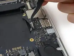
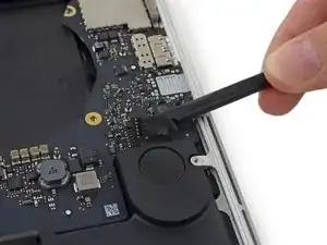
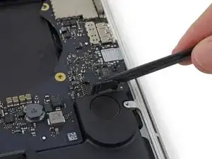
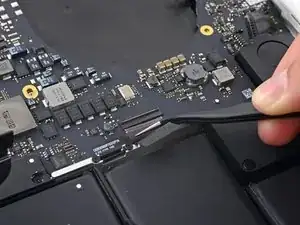
    • Utiliza el extremo plano de un spudger para levantar el conector de altavoz fuera de su zócal en la placa lógica.

    • Asegúrate de hacer palanca en el conector de cable y no en el zócalo en la placa lógica ya que si haces palanca en el zócalo podría separarlo de la placa lógica.

    • Con cuidado dobla el cable hacia arriba y fuera del camino de la placa lógica.

    this cable was stuck down, so I had to wiggle the spudger under the cable first to separate the adhesive. Then it came away easily.

    Pete Bagnall -

    Same here, the cable was stuck down pretty. Thanks Pete, your advice helped a lot.

    Al Moulder -

  8. HZpHp2FnRNDY2iYZ
    HZpHp2FnRNDY2iYZ
    QwmCjQI1mPgHGfZM
    • Retira la cinta que cubre la parte superior del conector de cable de datos del teclado.

  9. OyKCVZGB5MsPBycV
    OyKCVZGB5MsPBycV
    Y3KwHS1pHCJKbeds
    26Q2B2AYFPjQvjDJ
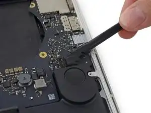
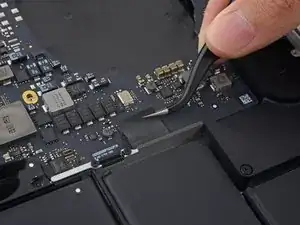
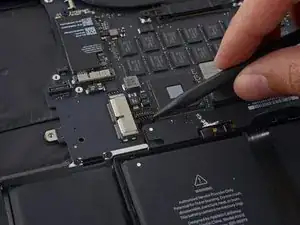
    • Usa la punta de un spudger para voltear la lengüeta de retención en el zócalo ZIF del cable de datos del teclado.

    • Asegúrate de no hacer palanca en la lengüeta de retención con bisagra y no en el zócalo en sí.

    • Tira el cable de datos del teclado fuera de su zócalo ZIF. Asegúrate de tirar paralelo a la placa lógica y no directamente hacia arriba.

    The retaining flap broke on me during reassembly. I was careful, but it kind of got stuck. Pay extra attention and if it doesn’t give, don’t force it.

    vincentdrummer -

    Same thing happened to me. Didn’t really put much pressure either.

    meadowsd -

    Same there here.. I ended up using some tape to ensure the cable stayed seated upo nreassembly

    Alan Dike -

    hey its not a kick, take it easy on it. after replacing my battery my keyboard (and not Richards keyboard) and track pad are non responsive, Russell Stewart old neighbour .

    Russell G Stewart -

    The last picture doesn’t show it but my cable had blue plastic material on both top and bottom, which I had not noticed during disassembly. It slid in nicely but now not sure if it is an insulating material of some kind that should have been set aside?

    Bill Klemme -

    I can confirm blue colour of cable tip.

    Mighty Sashiman -

    The retaining flap broke off on us during reassembly also…we (husband/wife team) were very careful, but the center piece just broke out when we applied pressure. the blue material did fit under the cable socket (like a smooth blue ribbon), but without the retaining lock, was unsure it would stay in position. We pulled the tape over it and hoped all would work. Everything seems to be working fine for us.

    Ann Brainard -

    The retaining flap broke on me as well and caused a near panic. I actually managed to fix it by careful inspection under magnifier and some trial and error with tweezers. The retaining flap itself is comb shaped - a solid edge and then combs that come out between the wires., and apparently just held in by the tiniest of detents. After trying unsuccessfully to push it back down between the wires, I surmised that the gaps in the “comb” side for the wires were sealed loop and that the wires it sat on were open ended. So I eventually ended up lining the flap up as if it were closed, and then carefully nudging it up onto the top wires, which was succesful, and then pushing it back into the open position to get the detents in place. Then to close it after reinserting the cable I walked it down bit by bit by pushing forward and *downward* on each side to help it maintain it’s ‘hinging’ effect. I think frankly you’re better off pushing larger ones like these down with your finger instead of a tool.

    Matt Fisher -

  10. NDYJfgEhIaTjnaUN
    NDYJfgEhIaTjnaUN
    liQdmwrTgdeLOVJG
    tnHQNkcsefaqHOC4
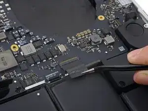
    • Usa la punta de un spudger para levantar el conector de altavoz derecho de su zócalo en la placa lógica.

    • Asegúrate de hacer palanca en el conector de cable y no en el zócalo de la placa lógica ya que si haces palanca en el zócalo podrías separarlo de la placa lógica.

    • Con cuidado dobla el cable hacia arriba y fuera del camino de la placa lógica.

    There's not much space here to work with. I found it helpful to remove the screws holding down the battery board, which allowed it to be lifted out a bit for easier access to this connector.

    maccentric -

    I used the tweezers on this and that was very effective in popping this cable out.

    Al Moulder -

  11. S2sBUZtwQh64VTip
    S2sBUZtwQh64VTip
    RX4xRMjdqlqKTDMj
    • Utiliza la punta de un spudger para levantar el conector de luz posterior del teclado de su zócalo en la placa lógica.

    On reassembly it would be great to have some tips on how to properly locate this connector…it’s kind of fussy.

    Bill Klemme -

    Thanks for calling this out. I took a picture of the socket after disconnecting. I can see why it might have been less obvious on reassembly.

    David Carroll -

    Also on reassembly - when putting in the logic board make sure this connector is not underneath. Once you have the logic board in, double check and if needed you can slightly lift up the logic board (like to take it out) and use the spudger to scoop it out.

    Jason Joyner -

    I found that this was actually really easy to get back on by using my finger instead of a tool, as I could just wiggle it back and forth slightly until I felt it seat. Hopefully using your fingers isn’t verboten - I was strapped in at the time and everything worked out in the end.

    Matt Fisher -

    the picture is mirrored

    Daniel Luescher -

    The picture is not mirrored if you see the heat sink that curves to the up and left it is not mirrored.

    Will Greider -

  12. BuAmdDqEMCpcWyxb
    BuAmdDqEMCpcWyxb
    mD3dQrBeODOJ5wlN
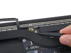
    • Utiliza la punta de un spudger para voltear el bloqueo de cable de datos de la pantalla y rotarlo hacia el lado del Power Port MagSafe 2 de la computadora.

    +(mit dem schwarzen Klebeband zusammen)

    Verwende die Spitze eines Spudgers, um den Verschluss des Displaydatenkabels nach oben zu klappen (mit dem schwarzen Klebeband zusammen) und ihn in Richtung MagSafe 2-Powerport zu drehen.

    Mihály Plajner -

    My mid-2015 has a flexible plastic tape on the cable lock bar, pulling the tape up with tweezers easily rotated the locking bar.

    prreitz -

  13. VBKUIUvAUB2riq6t
    VBKUIUvAUB2riq6t
    rmIXrN5PAVLVIN5R
    WCcAUuooVfJWHnPy
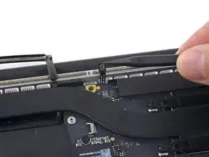
    • Saca el cable de datos de la pantalla de su zócalo en la placa lógica.

    • No levantes desde el cable de datos de la pantalla ya que su zócalo es muy frágil. Tira del cable de manera paralela a la faz de la placa lógica.

    • No toques los contactos en el conector de datos o su zócalo con los dedos o cualquier herramienta, ya que podrías depositar aceites o dañar las clavijas.

    • Dobla cuidadosamente el cable de datos de la pantalla hacia la bisagra de la pantalla para exponer los tornillos de la placa MagSafe 2.

    The wording of the instruction: “Pull the display data cable STRAIGHT OUT of its socket on the logic board” could lead to errors. It almost happened to me.

    Instead you should word it: “Pull the display data cable parallel to the face of the logic board being careful to keep it straight and NOT LIFT UP on the cable”.

    I realize you mention it later in the warning immediately below, however, by first saying “pull the cable straight out” leads to confusion and could lead the user to attempt to interpret “PULL STRAIGHT OUT” as “PULL UP” unsuccesfully only to later notice, maybe after breaking it, that there was a warning.

    Wording it properly the first time will make the warning unnecessary.

    Robert Habib -

    I had the same thought as I almost proceeded without noticing the red text warning.

    I especially think the second warning about not touching the contacts on the data connectors should be listed before the instructions on removing it.

    David Carroll -

    Agree with Robert. Suggest “SLIDE the display cable to the right, out of its socket…” would be less misleading.

    prreitz -

    I think it bears repeating just how fragile this connector is, particularly on reinsertion. The problem isn’t just technicians touching the connector end; you can damage the pins simply by inserting it slightly out of alignment, or at an angle, because the outermost pins are VERY close to the edge and are very fragile. They have the appearance of being embedded in the connector but they’re actually spring traces just lying on top of it. I managed to bend the southmost pin upwards reinserting it; luckily it flattened out again and worked, but if it had not been possible to do that it’d have been a whole new screen assembly.

    Jerome -

    I’m pretty sure I inadvertently touched the connectors. Would this cause immediate errors or obscure, difficult-to-diagnose problems later in life ? Also strongly suggest using magnification when disconnecting and reconnecting this connector and others to ensure proper alignment. As Jerome said these are some of the most fragile parts of the system.

    Matt Fisher -

    I'm jumping on the bandwagon here and saying that yes, pull the cable out towards the right (where the MagSafe connector) and not up. I also found using the tweezers made this easier.

    Big fan of the tweezers.

    Al Moulder -

  14. 5U2PaQkFStGhYWYI
    • Remueve los dos tornillos Torx T5 de 4.0 mm de la placa MagSafe 2.

    I didn’t take these out - just lifted the mainboard away and set it to the back while I removed and replaced the left speaker.

    Troy Havard -

    on my Mid 2015 MBP the MagSafe 2 board is wired to the logic board on the underside (keyboard side) so the screws had to come out. The following photo showing the logic board coming out does not show the MagSafe 2 board, so there is clearly some variation between these models.

    Richard Bugg -

    Richard, mine too.

    prreitz -

  15. rhihobaBENtlBfBs
    rhihobaBENtlBfBs
    KciyQfTCURsqMrJF
    X6wLXv2Z3GVpruaH
    • Levanta y tira el ensamblaje entero de la placa lógica de la pared de la caja superior.

    • Al volver a ensamblar, asegúrate de alinear los puertos con sus siluetas en la caja superior.

    When reassembling, be careful not to leave any cables (such as keyboard backlight connector, step 36) under the board.

    Andrey Pirozhenko -

    I had to tape most of the cables out of the way while reinstalling the logic board, because they kept returning to their plugged-in shape under the logic board as I tried to position it properly.

    Jamie Flournoy -

    Also, make sure to align the right (and left) I/O properly, making sure the tabs on each port are underneath the lip of the aluminum frame. In my case, I couldn’t push the logic board far enough to align the screws until I had done this.

    Alek Curless -

    Yes. This step is crucial. Thanks for pointing it out!

    jonvdez -

    I was struggling to align it and was beginning to get frustrated. I had to look back at photos to make sure the tabs had to go under the lip of the aluminum frame. Unfortunately I read your comment after the fact. Thank you.

    Robert Habib -

    if you’re only removing the right speaker, no need to remove the logic board. Simply lift the edge of the logic board to remove the speaker cable.

    Gareth Jones -

    I had to remove one of the screws from the battery board before the logic board had enough clearance to lift up.

    Jim Guyton -

    We (husband/wife team) just slid the logic board out to right, and did not entirely remove. For reassembly, we reviewed all the cables and made sure they were positioned out of the way, or taped back, before repositioning the logic board back into position. Worth it to review before getting it back into position.

    Ann Brainard -

    There are 2 more screws to be removed before the motherboard comes out. One were SSD was and one at 40 Degree position to right fan. It has a golden base ring. Easy to spot

    anupraje -

    Yes, I missed those two screws from Step 29 -- funny that we both missed that!

    kevin -

    Does the logic board prevent us from removing the battery? I’m trying to figure out why we are removing it.

    John Sikking -

    I agree John, tearing everything out is more of a risk then could be done ungluing the battery

    Russell G Stewart -

    Because the acetone can damage the board and connections -- in case of accident ;)

    kevin -

Conclusión

Para volver a ensamblar tu dispositivo, sigue estas instrucciones en orden inverso.

Andrew Optimus Goldheart

Miembro Desde 17/10/09

494159 Reputación

0 comentarios