Introducción
Usa esta guía para cambiar el tablero de botones derecho en la Steam Deck.
Recuerda: seguir los procedimientos de seguridad contra descargas electrostáticas (ESD) generales mientras reparas tu dispositivo.
Estos pasos solo describen cómo retirar y reemplazar físicamente la placa de botones de la consola. Es posible que necesites herramientas de software y procedimientos de calibración adicionales para obtener una placa de reemplazo que funcione según lo previsto.
-
-
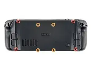
Utiliza un destornillador Phillips para retirar los ocho tornillos que sujetan la tapa trasera:
-
Cuatro tornillos de 9,5 mm
-
Cuatro tornillos de 5,8 mm
-
-
-
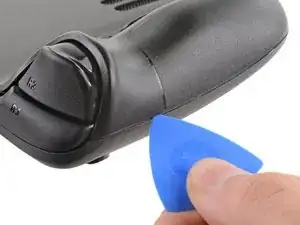
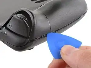
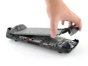
Inserta una púa de apertura en el delgado hueco entre la tapa trasera y la carcasa delantera, a lo largo del borde de la empuñadura derecha.
-
Haz palanca en la tapa trasera para liberarla de los clips de bloqueo.
-
-
-
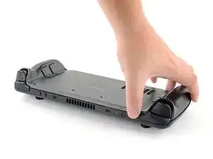
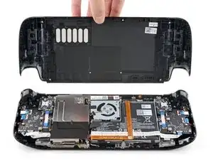
Agarra la tapa trasera por la abertura que acabas de crear y tira de ella hacia arriba y lejos del dispositivo para desenganchar los bordes largos.
-
Retira la tapa trasera.
-
-
-
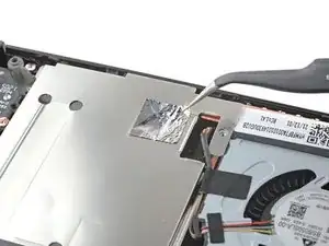
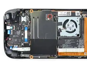
Utiliza unas pinzas para retirar el trozo de cinta adhesiva que cubre el tornillo oculto del escudo de la placa.
-
-
-
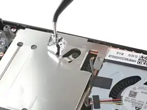
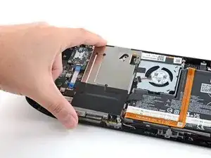
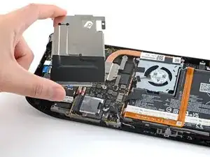
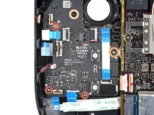
Usa el destornillador Phillips para retirar los tres tornillos que sujetan el escudo de la placa.
-
Un tornillo de 3.4 mm
-
Dos tornillos de 3.7 mm
-
-
-
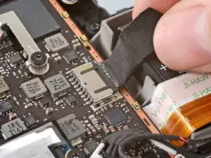
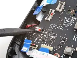
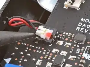
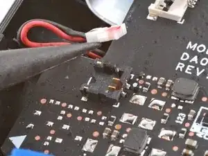
Agarra el cable de la batería por su lengüeta y tira de él directamente hacia fuera de la placa madre para desconectarlo.
-
-
-
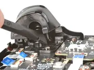
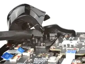
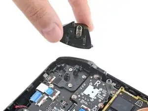
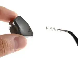
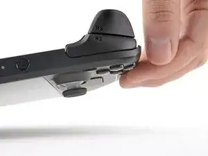
Coloca el extremo plano de un spudger en el borde interior del clip derecho del gatillo.
-
Gira el clip del gatillo hacia fuera, alejándolo y levantándolo de la clavija para desengancharlo.
-
-
-
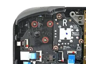
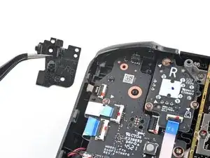
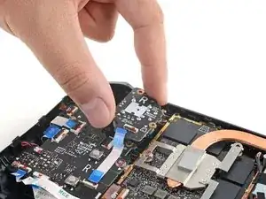
Utiliza un destornillador Phillips para quitar los tres tornillos de 5,2 mm, que sujetan el soporte derecho del gatillo.
-
-
-
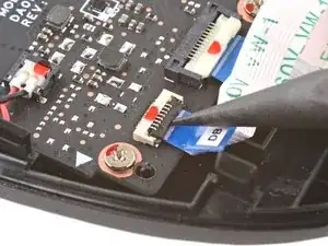
Usa el extremo puntiagudo de un spudger, para levantar la pequeña solapa de bloqueo en el conector ZIF del cable del stick.
-
Usa un par de pinzas, para sacar el cable de su conector.
-
-
-
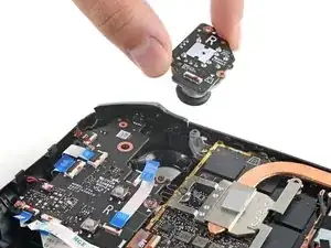
Usa un destornillador Phillips, para quitar los tres tornillos de 5,2 mm que sujetan el stick analógico.
-
-
-
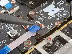
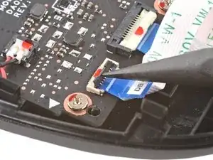
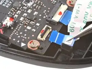
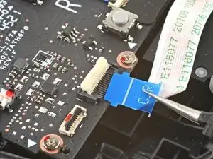
Usa el extremo puntiagudo de un spudger, para levantar la pequeña solapa de bloqueo en el conector ZIF del cable del tablero de botones.
-
Usa un par de pinzas, para sacar el cable de su conector.
-
-
-
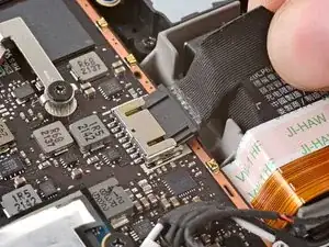
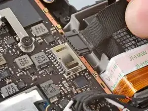
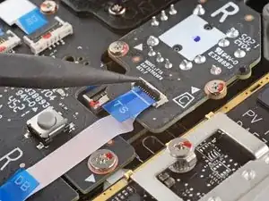
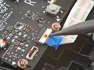
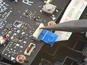
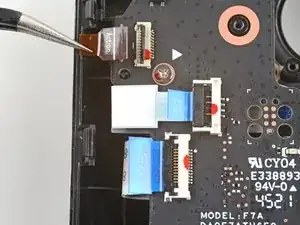
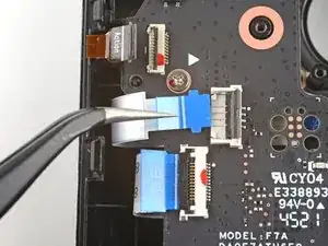
Usa el extremo puntiagudo de un spudger, para levantar la pequeña solapa de bloqueo en el conector ZIF del cable de interconexión del tablero de botones.
-
Usa un par de pinzas, para sacar el cable de su conector.
-
-
-
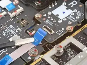
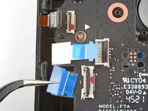
Usa el extremo puntiagudo de un spudger, para levantar las pequeñas aletas de bloqueo del resto de los conectores ZIF del tablero de botones. Usa un par de pinzas, para sacar los cables de sus conectores:
-
Desconecta el cable de los botones de acción.
-
Desconecta el cable de la placa del panel táctil.
-
Desconecta el cable del panel táctil.
-
-
-
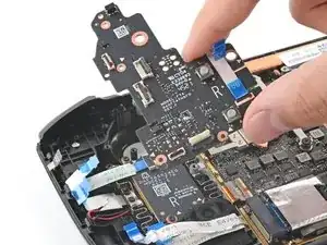
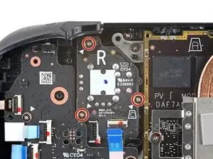
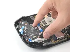
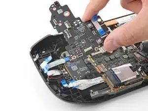
Usa un destornillador Phillips, para sacar los cuatro tornillos que sujetan el tablero del botón derecho:
-
Tres tornillos de 5,2 mm
-
Un tornillo de 3,9 mm
-
Para volver a montar el dispositivo, sigue estas instrucciones en orden inverso.
Lleva los residuos electrónicos a una centro de reciclaje certificada.
¿La reparación no salió según lo planeado? Prueba algunas soluciones de problemas básicos o pide ayuda a nuestra comunidad de respuestas de Steam Deck.

17 comentarios
When will this part be available?
Is there any update to when this part will be available?
Will this part not be available due to their need being a special calibration or hardware step? Having past six months this makes one think the part is not possible with end user due to another factor.
zZz -