Introducción
Sigue esta guía para cambiar los botones conductivos de goma y los botones exteriores de encendido y volumen.
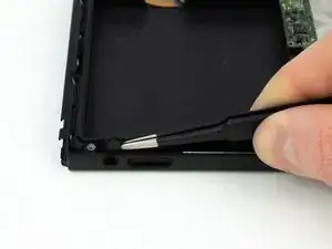
Cuando vuelvas a instalar, junta los botones exteriores de plástico a la almohadilla conductora de goma e insértalos juntos en la consola.
-
-
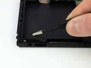
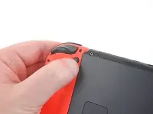
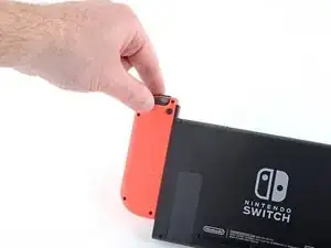
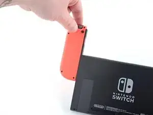
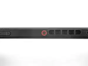
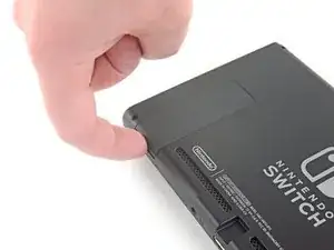
Mantén pulsado el pequeño botón redondo de la parte trasera del mando Joy Con.
-
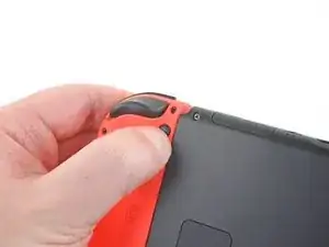
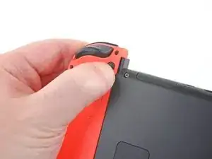
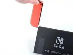
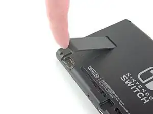
Mientras mantienes pulsado el botón, desliza el mando hacia arriba.
-
-
-
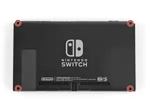
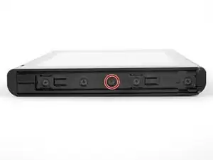
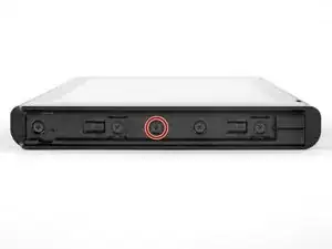
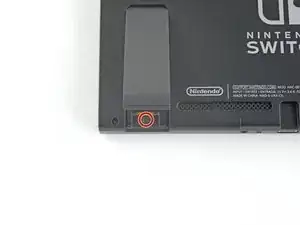
Utiliza un destornillador Y00 para retirar los cuatro tornillos de 6.3mm de longitud que sujetan el panel trasero.
-
-
-
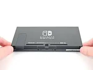
Utiliza un destornillador JIS 000 o un destornillador PH000 oficial de iFixit para retirar los siguientes tornillos que fijan el panel trasero:
-
Un tornillo de 2.5 mm de longitud en el borde superior del aparato.
-
Dos tornillos de 2.5 mm de longitud en el borde inferior del aparato
-
-
-
Usa un destornillador JIS 000 o un destornillador PH 000 oficial de iFixit para retirar los dos tornillos centrales de 3.8 mm situados en los laterales del aparato (uno en cada lado).
-
-
-
Utiliza un destornillador JIS 000 o un destornillador PH 000 oficial de iFixit para retirar el tornillo de 1.6 mm en el pozo de la pata de cabra.
-
Cierra el soporte.
-
-
-
Abre la solapa del cartucho de tarjetas de juego.
-
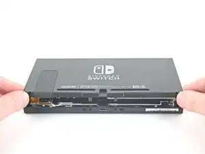
Levanta el panel trasero desde la parte inferior del dispositivo y retíralo.
-
-
-
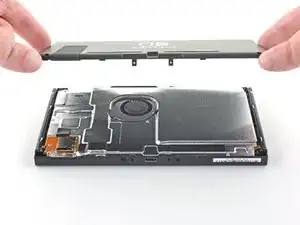
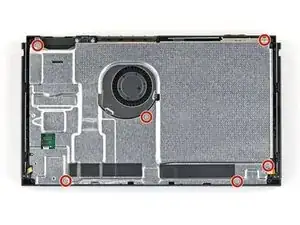
Usa un destornillador JIS 000 o un destornillador PH 000 oficial de iFixit para retirar los seis tornillos de 3 mm que fijan la placa de protección al aparato.
-
-
-
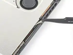
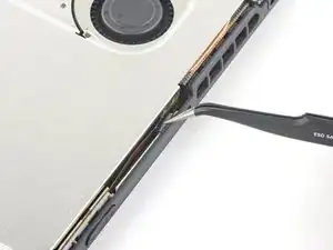
Utiliza tus dedos o unas pinzas para despegar el trozo de espuma que hay en el borde superior del aparato, cerca del puerto de salida del ventilador.
-
-
-
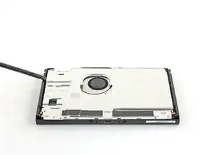
Inserta un spudger debajo de la placa de escudo a lo largo del borde del dispositivo.
-
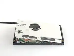
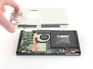
Haz palanca para levantar la placa de escudo y removerla del dispositivo.
-
Puedes reutilizar el compuesto térmico rosa si tienes cuidado. Mantén el compuesto limpio y asegúrate de que haces un contacto sólido entre el disipador de calor y el protector durante el montaje.
-
Si necesitas reemplazarlo, consulta nuestra guía de pasta térmica para quitar el compuesto térmico antiguo y reemplazarlo con un compuesto apropiado, como K5 Pro, durante el reensamblaje.
-
-
-
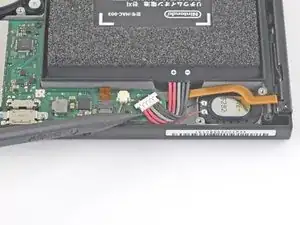
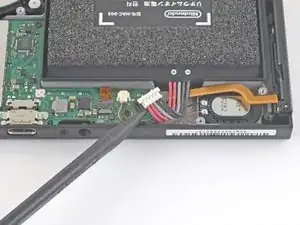
Usa la punta de un spudger para hacer palanca en el conector de la batería hacia arriba y fuera de su zócalo en la placa madre.
-
-
-
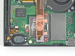
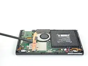
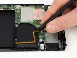
Usa un destornillador JIS 000 o un PH 000 oficial de iFixit para remover tres tornillos de 3 mm asegurando el disipador a la placa madre
-
-
-
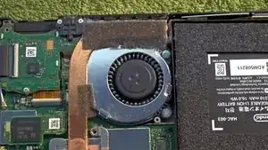
Despega con cuidado las dos piezas de espuma pegadas sobre el disipador y el ventilador.
-
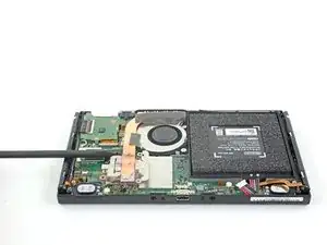
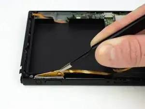
Introduce la punta de un spudger debajo de la parte de la espuma que no está pegada a nada,
-
Presiona la parte superior de la espuma con el dedo para mantenerla en su sitio.
-
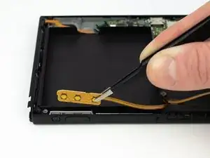
Pasa la punta del spudger por debajo de la espuma hasta el otro extremo de la espuma para liberarla.
-
-
-
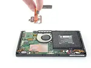
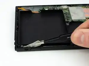
Usa una spudger o tus dedos para levantar el disipador arriba y fuera de la placa madre para removerlo
-
Aplica pasta térmica a todas las superficies a las que se les haya aplicado pasta térmica anteriormente. Esto incluye entre el tubo de calor y el escudo de aluminio, que el Switch usa como disipador de calor adicional.
-
-
-
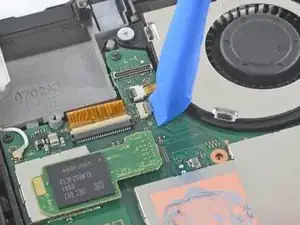
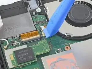
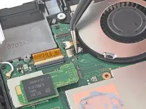
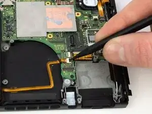
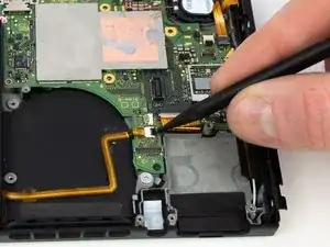
Use una herramienta de apertura, un spudger o la uña para levantar la pequeña solapa de bloqueo en el conector ZIF del ventilador
-
-
-
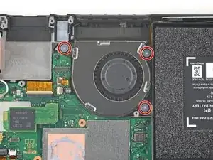
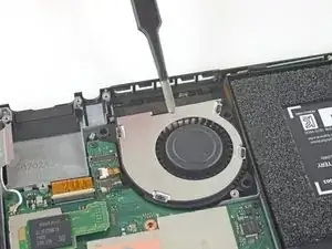
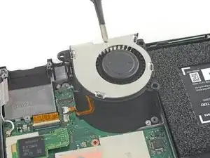
Usa un destornillador JIS 000 o un controlador oficial iFixit PH 000 para remover los tres tornillos de 4.8 mm asegurando el ventilador
-

Para volver a montar tu Nintendo Switch, sigue estos pasos en orden inverso, desde el final hacia arriba.

3 comentarios
What happens if the small black locking flap breaks?
Two angles are congruent if they have the same measure. You already know that when two lines intersect the vertical angles formed are congruent. You have also seen that if ∠A and ∠B are each complementary to ∠C, then ∠A ~= ∠B. There are other angle relationships to explore. When you expose these angle relationships, you will establish their truth using a formal proof.
Qui Ma -
This guide is missing the steps to Remove the microSD card reader and the steps to Remove the headphone jack and game card reader