Introducción

Los botones del controlador Nintendo Switch Pro y el D-Pad son las entradas principales del controlador. Es posible que sea necesario reemplazar los botones si no responden. Consulta nuestra guía de solución de problemas para obtener más información.

Durante el desmontaje, ten cuidado con los bordes afilados, hay algunas piezas de plástico expuestas que podrían cortarlo.

  1. iaKRfcPV2HNC5yUK
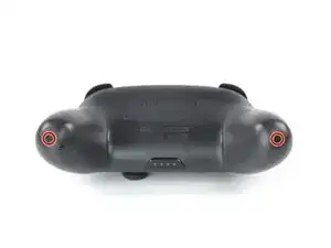
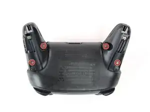
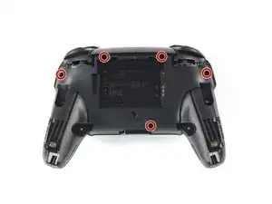
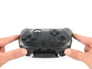
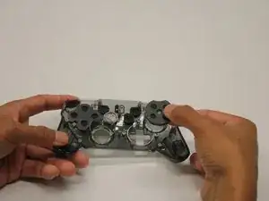
    • Voltea el mando para que las pegatinas de los modelos estén orientadas hacia el techo.

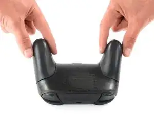
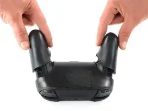
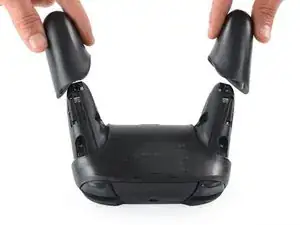
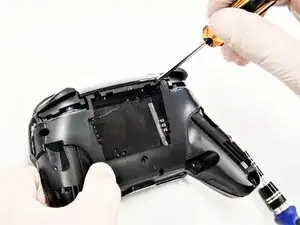
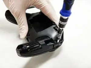
    • Usa un destornillador JIS #00 para quitar los dos tornillos negros de 8,4 mm que sujetan las manijas, ubicados en los extremos de las manijas.

    Be carefull, these screws are super easy to strip even with the right tools.

    Lukas Eberharter -

    I tried editing these instructions after I had trouble with stripping screws, but it doesn't seem to take. The issue is that these are JIS and not Phillips screws. They are VERY similar looking but a Phillips head screwdriver will strip the screws.

    Isaac Webb -

    I tried using a Philips #00 screwdriver but it didn’t work

    vincent ingrassia -

  2. pFHHOlTyvlQ43DOC
    pFHHOlTyvlQ43DOC
    KCE54LsPyGnuWTkW
    UNYZtREEKVfHallZ
    • Retira con cuidado las tapas de las asas separándolas del cuerpo principal.

  3. 3OnYDcOU1gVR2fEG
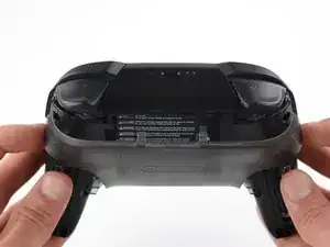
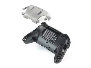
    • Utiliza un destornillador JIS n.º 00 para quitar los cuatro tornillos plateados de 6,8 mm que sujetan la cubierta de plástico transparente posterior.

  4. Zb3Ool4Evh63KKVd
    Zb3Ool4Evh63KKVd
    E4qBEgOibCQbXlIJ
    jihxJQfDSqclVJnF
    • Retira con cuidado la cubierta de plástico transparente con la uña.

  5. p4bHAkTpIvuBFIfc
    • Retira la cubierta de plástico transparente.

  6. yUbMYllrTC6sSOGL
    yUbMYllrTC6sSOGL
    6pxWhyQpxoXGbs22
    vEF6WXIGCHUebiZO
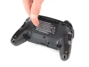
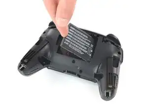
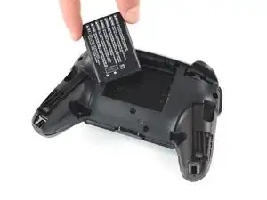
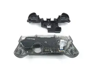
    • Retira la batería de iones de litio haciendo palanca con una uña o una herramienta de apertura de plástico en el lado izquierdo.

    • Sólo se necesita una pequeña cantidad de fuerza.

  7. 41hYi1SofYMKVF4B
    41hYi1SofYMKVF4B
    IhtOVVcrnx5IBHgJ
    WJ4LvGQlKLhlREns
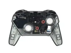
    • Usa un destornillador Phillips para quitar los cinco tornillos de 5 mm de largo de la parte posterior del controlador.

    the 2 screws up at the top are unreachable with the standard fixit kit just a heads up

    drew -

    Seconded. the screws are located too deep below the plastic slot, and the bit holding bulge is too wide for the small aperture (similarly with the flexible extension). the bit length is too shallow to reach.

    An alternative driver with a much narrower & longer shaft is required, which will likely not come with interchangeable bits.

    Douglas Selby -

    I would say it is possible to reach the top left screw, just not the top right - there is a gap in the top left that allows you to slightly bend the standard driver outward to turn it while still making adequate contact.

    El_Mechacontext -

    An update: I was actually able to remove the top right one in a really hacky way - inserting the Phillips #0 bit into the #4 hex bit, and then using that in the standard driver. This added just enough length to successfully reach and make full contact with the screw!

    El_Mechacontext -

    Using the #4 hex bit as an extension was the exact "hack" I needed to get rid of the drift finally. Thank you. You're a lifesaver.

    Das #4 Hex Bit als Verlängerung für das Kreuzschlitz Bit zu nutzen ist zwar etwas eng, aber es erspart einem wirklich einen zusätzlichen Schraubendreher.

    Techn0magier -

  8. PnIrdtdY4KCyxuKK
    PnIrdtdY4KCyxuKK
    ZBKtxPXnhQuBTaDN
    OZcevYGCPPARFaRx
    • Retira con cuidado la cubierta de plástico del controlador.

    • No quites por completo la cubierta frontal todavía, ya que todavía está unida a la placa base a través de un cable plano blanco.

    Didn't realize there is adhesive holding the front cover onto the unit. It's located inside of the handles. Just a bit of force there helped, just be careful of the cable.

    Roger Perez -

  9. NpVhXDsYSWmW4tBT
    NpVhXDsYSWmW4tBT
    QXe1DlCMuCXbrveX
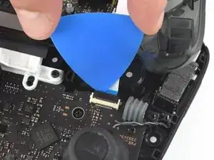
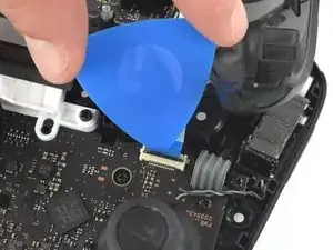
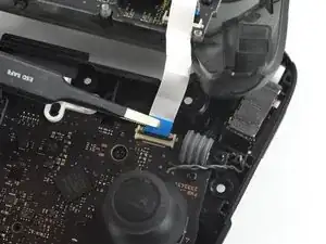
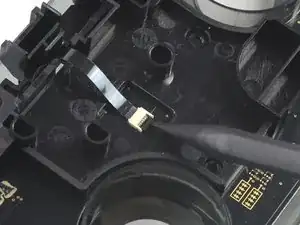
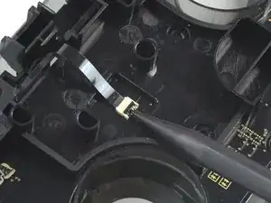
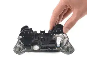
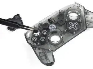
    • Usa la punta de una púa de apertura para abrir la solapa negra del conector ZIF empujándolo hacia arriba

  10. 3qj6VtFJtKAHHm6I
    3qj6VtFJtKAHHm6I
    YJvaLXngDhvHF1Gr
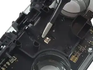
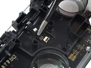
    • Usa tus dedos o un par de pinzas de punta roma para desconectar el cable de interconexión de su conector.

  11. OpC2vBHXBB35uAQ4
    • Retira la carcasa frontal.

  12. d2TaQbKySN1dMQ4M
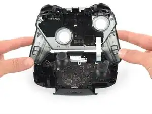
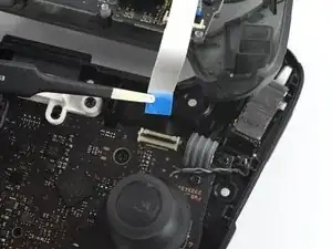
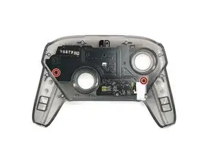
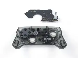
    • Retira los dos tornillos de 6,8 mm de largo en la placa de circuito superior con un destornillador Phillips.

  13. GuqsGsnEcB2nVvxX
    GuqsGsnEcB2nVvxX
    RVyZNQZQ3Depk22x
    • Usa un spudger para levantar la pestaña de bloqueo del conector ZIF.

  14. tlAmOo6KaKA6USWf
    tlAmOo6KaKA6USWf
    6GTbU2NmR3QpSBZC
    • Retira el cable plano negro de su conector.

    • Solo se necesita una pequeña cantidad de fuerza para quitar el cable plano.

    What do I do if the connector snaps off? Is it fixable with solder or electrical tape or should I give up hope?

    Jack Frost -

  15. ZHXWOMSOZhgEMnTA
    ZHXWOMSOZhgEMnTA
    PgCpkYRsAuKmefFR
    • Retira los botones de activación de la cubierta de plástico.

  16. mQAqc4XVQEAXj2aA
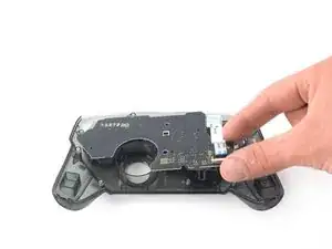
    • Usa un destornillador Phillips para quitar los dos tornillos de 5 mm de largo que sujetan la placa de circuito.

    There’s one more screw - in this picture, on the left. The junction of the body and left grip, right behind the ABXY buttons.

    Matt Rausch -

    Hi @mattrausch, thanks for your comment. You're right, the circuit board is held by two screws. I've updated this step.

    Adriana Zwink -

  17. TTTr1KChNOYWXFKp
    TTTr1KChNOYWXFKp
    IDKsaYYfvja4ScD6
    • Retira la placa de circuito.

  18. nTK2XeUsHIKxc31d
    nTK2XeUsHIKxc31d
    jqL5prVnGkp5QBPi
    25iVGNLUX1gUS6wZ
    • Usa tus dedos o un par de pinzas para quitar los botones que deseas reemplazar.

Conclusión

Para volver a armar tu dispositivo, sigue estas instrucciones en orden inverso.

James Seidlinger

Miembro Desde 10/10/19

572 Reputación

Un comentario

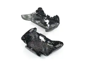
On re-assembly, you may have trouble getting the top circuit board and shoulder button support structure to snap into place. It’s easiest to get the circuit board around the right analog stick hole, and push it all the way down until it is in place, then to secure the shoulder button support structure.

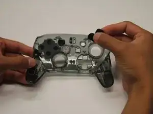
Make sure the “Home” button clear plastic light spreader (a clear irregular circle-shaped piece) is in place on top of the home button assembly, or it will give the home button a “sunken” appearance.

nclee -