Introducción

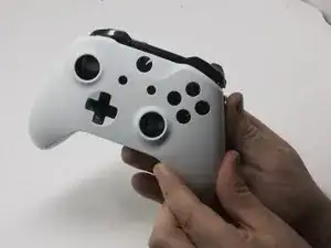
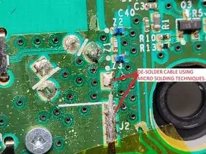
Es posible que debas reemplazar la placa base inferior de tu controlador Xbox si el controlador no funciona. La eliminación completa requerirá soldadura. El enlace a la guía de soldadura se incluye para ayudarlo. Esta guía te mostrará cómo acceder a la placa base inferior de tu controlador inalámbrico Xbox One modelo 1708.

  1. CZmZL2YuctGTuPJd
    CZmZL2YuctGTuPJd
    KHyRlDiLSFSdhQPm
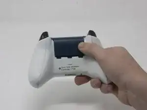
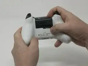
    • Desliza la tapa de la batería hacia la parte superior del control para retirarla.

    • Levanta las pilas o el paquete de pilas del compartimento de las pilas.

  2. 1RnNtaoQqQZkbY2E
    1RnNtaoQqQZkbY2E
    wVNiZ3TUwVBoC2FL
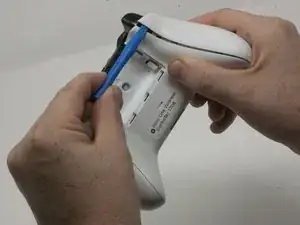
    • Inserta una herramienta de apertura de plástico en la costura superior y mueve suavemente la herramienta de apertura hasta la parte inferior del controlador.

    • Continúa usando la herramienta de apertura para sacar suavemente la placa lateral del controlador.

    • Repite este proceso para la segunda placa lateral.

    Only use a pry tool! The vibration motor wires are exposed and directly accessible from the side when opening. I attempted to open it with a small knife, expecting to be able to gently pry the clips open, accidentally sliced through my right motor’s wires.

    Sawyer Coe -

    Not a sharp of course.

    Kajus Slekys -

    If you have some Guitar picks laying around they work GREAT!

    Mike Beane -

  3. S6rlXDDRcqlumZ32
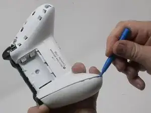
    • Despega suavemente la etiqueta de la batería o haz un agujero en el centro de la etiqueta en el compartimiento de la batería para revelar el tornillo oculto.

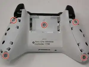
    • Retira los cinco tornillos de seguridad torx-9 de 9 mm de la parte posterior del controlador.

    Torx-8 security bits work as well.

    jahiamir -

    Torx 8 or 9 wasn’t working. I used 2.0 minus screwdriver

    richjlee -

    The 2.0 minus worked for me as well.

    metric -

    When sliding in the plastic cover during reassembly be sure it lines up with the battery compartment contacts. It can be really easy to not see it and bend the contacts. If you still encounter force during this step, depressing the triggers out of the way worked for me.

    Drew -

    Since mine is out of warranty I just broke out the security nib with a 2.0 standard bit. Then used a T8 torx.

    Tim LaCrosse -

  4. kfdJ5aNuDEUk4QSv
    kfdJ5aNuDEUk4QSv
    EaxhK2qZKFPa2bSP
    uLhJmZMFjIR1fmmF
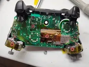
    • Pega con cinta los motores Rumbler/shock en su lugar.

    • Esto evitará que los motores se caigan.

  5. iqgdKTgD5ghZ2AiA
    iqgdKTgD5ghZ2AiA
    k5hd4bkef3GQZcnV
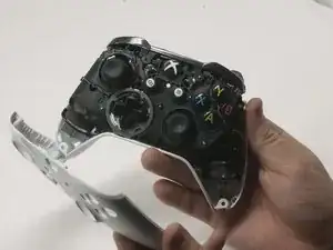
    • Orienta el controlador de modo que la placa frontal quede hacia arriba.

    • Levanta la cubierta frontal del controlador.

  6. jALZRgrIkQxcoU2w
    • Voltea el controlador boca abajo y levanta suavemente la placa trasera.

    Reassembly: When placing the back cover on: notice that the battery terminals need to slide inside the cover first. Then compress the triggers slightly, Then the cover will be aligned correctly. Then add the front cover and add screws so it doesn’t come undone.

    hunteil -

  7. K1gPMYdctQwIjRAw
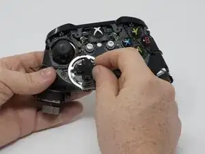
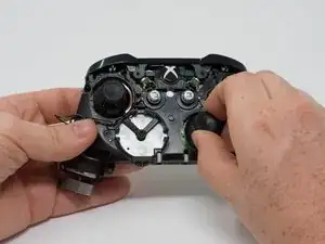
    • Da la vuelta al dispositivo y retira el teclado direccional tirando de él suavemente para separarlo del controlador.

    It needs to be made a little clearer that the thin metal retaining ring needs to be unclipped before pulling on the D-pad. A small, flatbladed screwdriver did it nicely for me.

    Paul Hough -

    As mentioned above, clarification is needed that the metal ring is intended to lay on top of the DPad - you should remove it first when disassembling, and it should be installed after the DPad to hold the DPad down when re-assembling.

    Additionally, the DPad is oriented so that the directional button without an extended tab on the end is on the bottom (down).

    sonofray -

  8. SBpFEREdAboEdgLe
    • Retira los joysticks del controlador.

    Are the joystick potentiometers soldered to the mother board or just push fit, this guide doesn’t mention soldering so I’m assuming the latter?

    Can you get genuine replacement joystick potentiometers as I’ve only seen cheap eBay type ones?

    Alan -

    The actual joysticks themselves are soldered into the bottom motherboard.

    Bryan Remely -

  9. 5t5KCuZPr2OMwC1f
    • Si los motores de vibración se salen del marco, los cables pueden desconectarse de la placa base. Los cables tendrán que ser soldados para volver a conectar el motor.

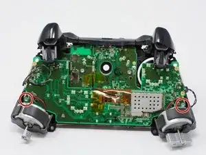
    • Voltea el dispositivo y retira los dos tornillos torx-6 de 7,0 mm en las esquinas inferiores izquierda y derecha.

    What if you don’t care about the rumble motors (always turn that feature off anyway), can I just leave them unattached?

    tracynoelle23 -

  10. pEbd1gIRs5PbH34d
    pEbd1gIRs5PbH34d
    1FZitJnwyeRqURT6
    c1vIJPoLSP2OT2FH
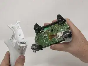
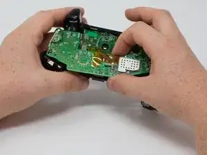
    • Sujeta con firmeza las placas base superior e inferior con manos opuestas y luego sepáralas con cuidado.

    • La placa base superior todavía está conectada a la placa base inferior. Para separar completamente la placa base superior, deberás usar un soldador.

    • Advertencia: No intentes desconectar el conector blindado (de color dorado) ya que es extremadamente frágil y lo romperás. Corre entre las dos placas.

    • Desuelda el cable blindado de la placa inferior en lugar de intentar desconectar el conector. Desuelda utilizando técnicas de microsoldadura.

    Soldering is not necessary for separation as on the top motherboard it uses a small connector commonly used in wireless assemblies for antennas. Simply pop it of using any prying tool or just your hand but make sure it is the side that has a gold or brassy finish and not a solder joint.

    Wyatt Faught -

    Hey Wyatt,

    Thanks for the feedback. I was on the team that authored this guide. I did not work on this specific guide so I am not familiar with this specific connector. I will follow up with iFixIt and check this issue. Thanks for the comment!

    Dylan Gross -

    Wyatt is correct that the black wire in the center can be removed from the top motherboard, but it doesn’t do any good to do so as there are two other sets of wires (grey and black twisted pairs leading to the left and right trigger) preventing you from removing the bottom motherboard entirely. These wires are visible in the pictures of this guide.

    Frank Buccella -

    I accidentally broke the part where the black wire connects to. Do I need to buy the top motherboard to fix this problem?

    drakeswifer -

    I can further confirm this as I have just pulled one apart. No soldering iron required.

    Brandon -

    What's is the name of the part for wireless on the controller

    justin edge -

    You'll see..

    Kajus Slekys -

    In my controller that black cable (the antenna like) was separated form the board is there any way to solder it again (the socket is still conected to plug)

    Dominik Gałczyński -

    I have the same problem. It popped off the board when firm pressure was applied to reconnect the wire after a repair. I'm going to attempt to apply a small bead of solder to the part that popped off, press it in place, and then heat the connector with my iron. But I am not hopeful at all. It's tight, really tight, and if it works it will be through luck alone.

    Michael Broder -

    Any luck? Theres no pad to get the solder to stick to on mine. Im assuming it is the j1 connection. Any idea what this wire is for?

    Matt Gribbin -

    Same issue here. I tried to unplug the antenna connector but the weak solder joints disconnected from the top motherboard instead. Looks like it has couple of bigger solder pads for ground/shielding(?) and one tiny pin in the middle for the actual antenna which can maybe still connect by pushing in place? Looks like a very difficult solder job as everything is so tiny.

    Kari Söderholm -

    Can someone help to find out the actual name of RF connector type?

    mntlzr -

    Hi i destroy black wire connector on top board please help me.

    Mohsen Heidary -

    It’s IPEX 4 connector, i've ordered bunch on chinese site and replaced mine. It was hard but doable.

    mntlzr -

    mntlzr : Thanks a lot for the connector type. More specifically it seems to be IPEX 4 SMD female socket on the top motherboard.

    Kari Söderholm -

    Hi yellow tape on board what

    Mohsen Heidary -

    How does the black wire reconnect? And is it necessary?

    Craig McBeth -

    I just put my controller back together (I opened it just to clean all the buttons since my son spilled some juice on it) and it seems to work wirelessly (with a PC using the dongle that came with the controller) even having broken the small black antenna cable connector off from the top motherboard. Not sure what that cable is used for or is it just an additional antenna for better connectivity. At least my controller still seems to work fine wirelessly without that cable being connected even from several meters away from the computer.

    Kari Söderholm -

    Actually nvm. Now that I tried the controller for a second time on the next day it seems to disconnect all the time so wireless is not working properly. I’ll need to try to fix the antenna cable by soldering. Probably will order a replacement connector (IPEX 4 SMD female socket) and try to solder that on.

    Kari Söderholm -

    1) TAKE HEED TO THESE WARNINGS AND BE VERY CAREFUL

    2) Instead of separating the boards completely all you need is to get enough space to pull the part out.

    *WHILE HOLDING WITH BOTH HANDS AS IF YOU WHERE PLAYING AND PUSH THE TOP BOARD FORWARD WITH YOUR THUMBS LIKE A DRAWER AND THEN LIFT UP!

    IT WILL SEPARATE JUST ENOUGH TO DO WHAT YOU NEED. *THIS TAKES CARE, FINESSE, & SOME SKILL.

    TyGuy -

  11. FhCHVTkfS5JIUAS3
    FhCHVTkfS5JIUAS3
    Slj4rrSygUsbOU66
    • Retira el puerto de audio de la placa base inferior.

    Can you just leave out the audio port and use the controller or u have to have a replacement to play

    Itachi Uchiha -

    Why would you *need* the audio port? If you are happy to not use then fine, this is an instructional to get it working and by extension a headset one would assume.

    Ali J -

    This piece is just placed in there - sandwiched between the two motherboards. No adhesive, no mechanical attachment, nothing.

    Andrew Sauk -

    So can it be replaced or no? I took it out it dont look fried or anything but it still dont work when reinstalled

    Frank Minelli -

  12. cNONLRgZCbNGsnNB
    cNONLRgZCbNGsnNB
    6rDVhwtVxLEGDP6K
    kwrYYSRxFHDo4xOC
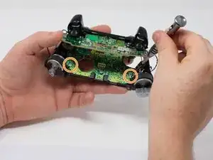
    • Retira los tres tornillos torx-6 de 70 mm del centro de la placa base inferior.

    • Retira los dos tornillos torx-6 de 70 mm junto a los motores de vibración en la placa base inferior.

    • Retira el tornillo torx-6 de 70 mm ubicado en el lado izquierdo de la placa base inferior.

  13. WRWQJIdAY3iRasrr
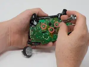
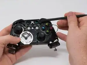
    • Usa un spudger de plástico para levantar el clip de plástico de las clavijas delanteras.

    • Retira el clip de plástico deslizándolo hacia arriba.

    Reassembly: This hard is hard to mount. Slowly flip the controller upto view the charging port and notice it isn’t aligned yet… If you force it to outside of pcb, it’ll try to pop off. I’ve yet to figure this step out… I forced it and after full reassembly, the bumpers became REALLY stiff.

    hunteil -

    Solution: Instead remove the outside piece mentioned in image… then remove the bumpers… Check that all cavities are clear. Then make sure the sync button is inserted all the way in… Then place the left bump in the far left hole first. Then ensure the horn part slides into it’s specific slot inside, then ensure the the sync button goes in hole…then continue to right bumper side…. Then add the over cover piece above it… Start with the piece that goes over the charge port. Then the front as the above image shows… Now check your bumpers for easy clicking… If it’s still not correct, remove and try again gently as the horns may snap off and the PCB may get damaged.

    hunteil -

    Note: I believe the order is very important or the alignments on the left side may have the horn forced into one of the other close cavities and you won’t even know it. (This causes that horn to get damaged over time too. Without the horn, the bumper will drift and miss the button and bind up the trigger.)

    hunteil -

    PS: Rubber band to hold triggers down slightly helped a ton! Otherwise the trigger is over extending into the bumper assembly space.

    hunteil -

  14. QiaHv1Y56eTQ1Rrl
    QiaHv1Y56eTQ1Rrl
    TPLNYnlCbHTeWXNN
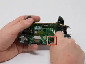
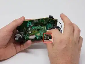
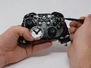
    • Usa un spudger para soltar los pequeños ganchos en cada extremo del parachoques izquierdo y derecho.

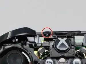
    • Después de soltar estos ganchos, ten cuidado al separar la placa frontal de la parte posterior del controlador. El botón de conexión/sincronización (vea la segunda imagen) está sujeto por esta placa frontal y se aflojará a medida que realices este paso.

    Watch for the tiny button that sticks out from the top - it’s the wireless connect/sync button.  It will fall out and is easy to lose.  During reassembly, I found it easier to put the bumper back in first, then use a tweezers to insert the button back into place.

    w.m. williams -

    Anyone know what part to look for when ordering replacements? I mean the switch itself, to solder it back on to the PCB

    Adam -

  15. 3lKUbADDACjL44bC
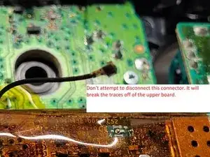
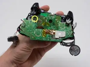
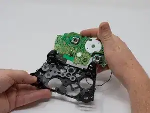
    • Para evitar desconectar los cables conectados a la placa base, levanta la placa base del marco de plástico como si abrieras una computadora portátil.

Conclusión

Para volver a armar tu dispositivo, sigue estas instrucciones en orden inverso.

Jesse Wilson

Miembro Desde 25/09/17

1749 Reputación

14 comentarios

Just to clarify you don’t need to do any soldering. If you are careful enough with the top mobo and rumble motors the wires should stay connected and you can take out the bottom mobo fairly easily. I saw some youtube videos that imply that you do need to disconnect and solder them back. Not the case!

James Williamson -

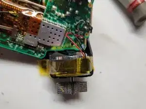
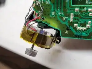
What is the wire that connects the two motherboards together with the copper adaptor for? When taking mine apart, the wire came loose from that tiny copper piece and is unrepairable. I think it's for the Bluetooth functionality. The wire used looks to have a very tiny wire inside itself surrounded with what looks to be ground wire. It's the black one in the middle.

crunchychipmunk90 -

It will clip back into place if you align it properly.its similar to the antenna clip of motherboard in a iPhone 4 you don’t need to solder it just lift and be careful when reattaching it don’t force it if it bends you are screwed. But when lined up right minimal pressure will snap back into place.

dankweedkilla -

I’ve tried many different angles and pressures to get that thing back in, the pin doesn’t look bent but it just won’t go back in.

Jason Bogart -

does anyone know part number for controller in which the mother and daughter board are connected with a ribbon cable? this one has a plug

i need to replace the ribbon cable connector. thoughts.

steve -

It looks like I'm not alone with broken RF connector case. Maybe someone had a success in repairing?

First need to find out the actual name of this connector type.

I think it's IPEX gen. 4 (MHF4), seems a fairly rare format.

IPEX gen. 1 (MHF) is much more widely spread, for example, in laptop network adapters, but it’s bigger.

mntlzr -

Quick question, anytime I repair controllers what is the wire that connects from the bottom motherboard to the top motherboard for?

Brian -

do you know if the r91 chip can cause the controller not to work even after new batteries are put in

Greg -

I have a problem putting my controller back together. The top mother board isn’t lining up properly it’s a lil too high up and it won’t let me put on the back

Dogslime -

Does anyone know if a motherboard from a different gen controller is compatible with the 1708 model or any at all? Like are they interchangeable or would i have to stick with that model specifically?

Miguel Mendoza -

After replacing the mainboard the controller doesn’t turn on with batteries nor by USB. Any Idea what did I did wrong?

Eric Molina -

The antenna connector on the board purchased from here will not connect to the other board…

josephtillman11 -

I just bought a replacement board and installed it with these instructions. I made sure not to let any connections become severed and put everything back together just like before. Every input was working properly, including the sync button (which triggered this replacement in the first place). However, for some unknown reason, the controller now drains one of every pair of batteries put into it in less than 12 hours. I opened it back up and saw nothing indicating a short circuit. What could be going wrong?

Christian Marmolejos -

I have a 1708 controller in Fortnite purple. The view button is INOP. I’ve seen many forums where people have the same problem and it seems to be very common. Does anyone actually know the cause..? What’s required to fix it? Please help.

Derek Jackson -