Introducción

El filtro EMI está instalado en el dispositivo y está detrás de algunos componentes. Debido a esto, hay muchos cables a su alrededor que no forman parte de este componente específico. Asegúrate de seguir cuidadosamente los cables y los componentes para asegurarte de que se extraen las piezas correctas.

  1. vKYkNXJG6EyYZXwb
    vKYkNXJG6EyYZXwb
    bdoSe25Kx2AEFnuf
    Fy6tFKoYcjhdx4uu
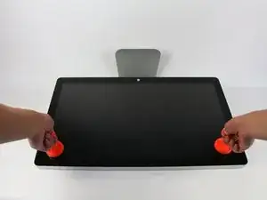
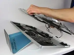
    • Coloca la pantalla con el lado de la pantalla hacia arriba.

    • Dado que la pantalla se puede inclinar hacia arriba y hacia abajo, nos resultó útil sostener la pantalla con un bloque de espuma de poliestireno entre la pantalla y la base.

    • Coloca las dos ventosas a ambos lados de la parte superior de la pantalla y asegúresate de bloquearlas en su lugar.

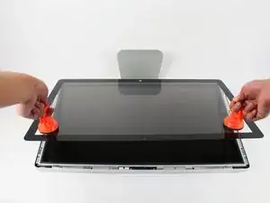
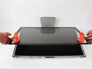
    • La pantalla de cristal está conectada al resto de la pantalla mediante pequeños imanes. Levanta lentamente y la pantalla se apagará de inmediato.

    Instead of $14 foam block, I used a full roll of paper towel and two pillows. While it worked, if I ever did this again, I would buy the block of foam. Since you’re removing a power cable, you need to be able thread it through and I think the foam block would make that easier.

    Josh Miller -

    You can also use a single handle, double cup floor lifting suction cup. Just place it in the centre of the screen near the camera and lift slowly.

    Steve A -

    I just used a toilet plunger to remove the screen and it worked like a charm!

    Philip Jacob -

    That’s what I call resourceful—made my day. I hope your repair was successful.

    Tobias Isakeit -

    Great idea, thanks a lot!

    Yvan Sandoz -

    The glass lifted off the magnets quite easily after just using my fingernails. No suction cups or toilet accessories needed.

    Adrian Gropper -

    I had the same problem and after removal of the fan and a bit of work with the vacuum, the fan is quiet. Thanks to ifixit for the great instructions that made this easy.

    John Perser -

    To keep the screen up, other soft objects might work, but it's important that the hole in the back isn't covered because you will need to thread the new Thunderbolt/MagSafe cable through it and it would be a hassle to do it after everything's been set up.

    Thomas -

    Anybody got any links to glass screen replacement supplier for the A1407 Thunderbolt Display? Im finding it impossible to find a replacement without it being crazy money.

    Michael McMillan -

    Instead of a wedge, I used 4 rolls of toiletpaper, one under each corner.

    jnbruin -

  2. y1QM4GJuH1vKrEUg
    y1QM4GJuH1vKrEUg
    xV1xJRpqEugIUYOL
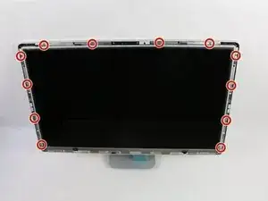
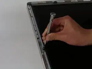
    • Desatornilla los 12 tornillos alrededor de los bordes laterales y la parte superior de la pantalla LCD con el destornillador TR 10.

    The screws marked in orange don't need to be removed, all they do is hold the magnets on the LCD.

    Garrett Mace -

    Yes “orange screws” does not need to be removed.

    You do not need a TR10 screwdriver as written in the text a T10 will suffice (more common and also correctly mentioned in the list of tools).

    A TR10 screwdriver is compatible with the T10, but not the other way around

    Per Lohmann Poulsen -

    On mine, the orange screws did hold the LCD down; the magnets were held in by TR6 screws, and those did not need to be removed.

    jml9904 -

  3. dNtDx1LZQDU1OVbo
    dNtDx1LZQDU1OVbo
    OSaiV2IVJO3u5HPx
    • Levanta lentamente la pantalla LCD de su ubicación e inclínala hacia arriba.

    • Puede ser muy útil tener un par de manos extra para sostener la pantalla LCD mientras trabajas con los cables debajo.

    • Hay cuatro cables que conectan la pantalla LCD con el resto de los componentes. Asegúrate de no tirar con fuerza y romper ninguno de los cables.

    Add the note that it should be lifted from the bottom edge. It is also important not to twist the display by levering up from one corner.

    Charlie Nancarrow -

    Before lifting the monitor, you should be prepared to start collecting screws and have your TR 10 ready.

    Josh Miller -

    Having a couple of short screwdrivers handy to prop up the LCD (like you would a car hood) while you disconnect the cables helps.

    jml9904 -

  4. vYMImIhPgImDC4sZ
    vYMImIhPgImDC4sZ
    KwPHhIYJrH6vl4ZA
    ltsqwLZEIXOkvKZf
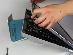
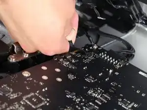
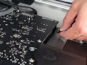
    • Para el primero de los cuatro cables (el más alejado del cable sujeto por un tornillo), sujeta el conector y tira lentamente.

    Note: be sure to pull away but not hard. Wiggle and pull slowly. These are delicate especially due to age.

    Overall this is a moderate repair. Follow step by step and you are good.

    Also, use tape and/or labels to mark which cables go where per the MLB and other parts. Resulting in easier reassembly.

    Ted Teske -

  5. aJXhUDyuRDBEYIPX
    aJXhUDyuRDBEYIPX
    TvkYkf3pUBHBJZEQ
    N6oVUvAxqymMUFXn
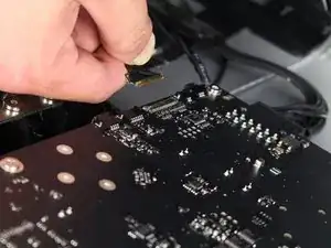
    • Para el siguiente conector, que está justo al lado del cable anterior, hay un trozo de cinta pegado a una barra de metal.

    • Voltea la barra de metal usando la cinta como manija.

    • A continuación, sujeta el conector y tira de él lentamente para sacarlo del zócalo de la placa lógica.

    What is this connector for?

    pdspanagel -

    I imagine this connector is going to be for display data (i.e. LCD data).

    Scott Havard -

    I pretty much mangled this cable trying to put it back into the slot. Is this something I can order a replacement for?

    Ryan Stryker -

    I also screwed up this wire.

    erybovic -

    I also screwed up this wire. Wondering what the wire name is.

    erybovic -

    Thunderbolt Display 27" LVDS Cable

    Klaus Finke -

    As other’s have said, this cable is super delicate.

    When you replace it, make sure that the small metal handle it firmly reattached to the other side of the port. I thought I’d got it right first time, but had no video signal (thunderbolt detected display, and power was fed to the Macbook Pro).

    I had to reinsert this one again, and one in, firmly press the connector home, then latch the handle over the other side. I also gave it a test pull to ensure it was secure. Then all was well!

    Steve A -

    Managed to remove it but broke one pin putting it back. I don’t understand why they make so fragile with all the space available…

    BAULARD -

    Can anyone provide a photo of this connector so as to give a better understanding of its mechanics? see this cringe worthy effort at guidance; https://youtu.be/A96CUSm_Xhs?t=1050

    Philip Sharp -

  6. yYhUxvsdBk3pv3Io
    yYhUxvsdBk3pv3Io
    EyjpfRYE2bE1xGWk
    a4reZswHC1EsBc11
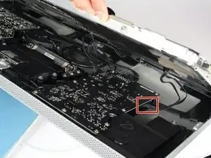
    • Para el conector del otro lado de la placa lógica, toma el conector por debajo y tira con cuidado de la placa.

    To remove this connector, you squeeze the lower tab to unclasp it, and pull it sideways away from the board

    Brad Bell -

    This cable was also taped for me, so remove the tape first

    danmcfalls -

  7. sjOHkIKEoj3IwvE6
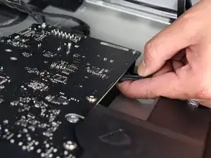
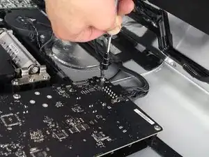
    • Para el último cable que se conecta a la pantalla LCD, usa tu destornillador T 10 para quitar el tornillo.

  8. fGJtJg1gy2EQTqVl
    fGJtJg1gy2EQTqVl
    XNFyMYy5JtA3VvQX
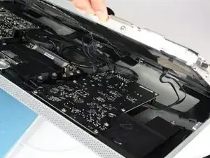
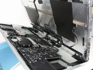
    • ¡La pantalla LCD ahora se ha desconectado por completo de la carcasa y se puede reparar/reemplazar!

    • es mejor colocar la pantalla LCD sobre una cama o sobre una toalla gruesa para evitar dañar la pantalla LCD

  9. IAdhOVeNuJYgWleN
    IAdhOVeNuJYgWleN
    dHys1ZnkrDAYMc4E
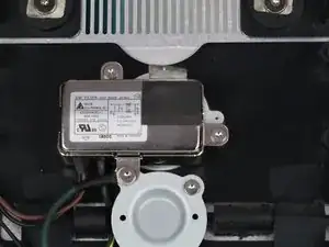
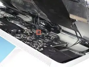
    • Ahora deberías ver el filtro EMI justo en el medio del dispositivo (aunque retenido por algunos otros componentes).

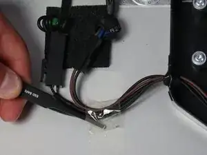
    • Sigue los cables que salen de la parte inferior del adaptador de corriente hacia la izquierda.

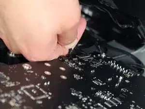
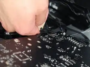
    • Toma las pinzas y retira el trozo de cinta que sujeta los cables a la carcasa.

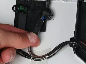
    • Solo hay un conector que debe sacarse (¡aunque hay dos uno al lado del otro!).

    • Agarra el conector por la parte inferior y sácalo con cuidado de su toma correspondiente.

    Note: The Brown/Black pair highlighted in the picture is for the AC connector. For the MagSafe power, you want to disconnect the double-black wire connection. Another way to distinguish if colors differ is that the MagSafe connection has a much larger connector on it.

    Isaac -

    Confirming what Isaac said. The black/brown pair don’t need to be unplugged. It’s the other connector that needs to be removed to replace this cable.

    R Miller -

    Yes - pictures and last bullet point are misleading and confusing respectively. I suggest fixit should remove the second picture and replace it with a picture of the connector that should be removed and amend the last bullet point o read something like 'depress the clip that holds the left connector in place and carefully etc ...'

    Avoid the verb 'grab'

    Philip Sharp -

    The plastic tape was completely dried out and had slight burs from overheating. Replaced with regular masking tape.

    Thomas -

    Confirming that pictures and last bullet point are misleading. The double-black wire connection is the larger connector and is black green. Much easier to tell apart and much easier to unplug.

    Thomas -

  10. f2eTfEXtKSnhjaFH
    f2eTfEXtKSnhjaFH
    ubeP3nSbSlSRj3Zl
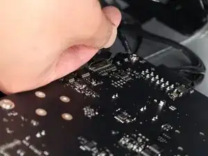
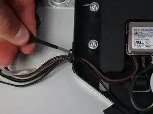
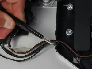
    • A continuación, retira el trozo de cinta aislante que sujeta los cables en la carcasa que se conecta al adaptador de corriente.

  11. fIwqSYHs6L4WiqS6
    fIwqSYHs6L4WiqS6
    NvKeWDj1ntTX5qGc
    1TeokRN3dFfD4tV2
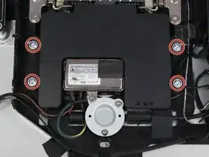
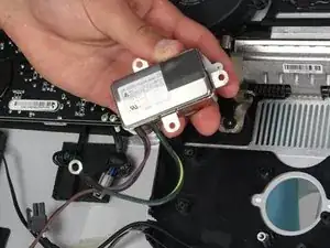
    • El componente del altavoz circundante (la caja negra) alrededor de la entrada de alimentación debe quitarse.

    • Utiliza el destornillador TR 10 para quitar los cuatro tornillos.

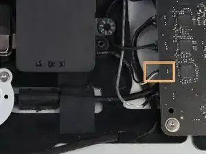
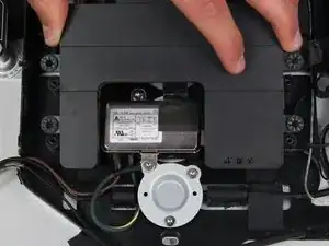
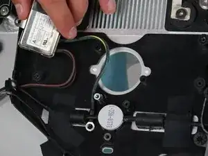
    • Desconecta el altavoz de detrás de la placa lógica tirando con cuidado del extremo de plástico del cable.

    • Retira el altavoz.

    If you are only replacing the Thunderbolt and MagSafe cable, steps 11-13 do not need to be performed ie speaker and EMI filter do not need to be removed, only the screw holding the grounding cable on the EMI filter (top left of round disk).

    martin baynes -

    I concurr with M Baynes.

    Macrepair SF -

    I just successfully removed and replaced the Magsafe/TB cable. I can confirm that Martin Baynes and lamajr are correct.

    Kevin -

    Can confirm martin baynes' comment, steps 11-13 are unnecessary.

    Thomas -

  12. Gmo3uGR1nvqYoULt
    Gmo3uGR1nvqYoULt
    uBvJstRwqGaA5Jce
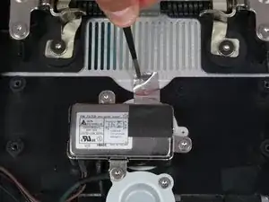
    • Ahora que el altavoz del medio está fuera del camino, se puede acceder fácilmente al filtro EMI.

    • Con unas pinzas, retira la cinta plateada que se encuentra en la parte superior del filtro.

    I can’t help but notice that this assembly that is called an EMI (Electromagnetic Interference) Filter is in the exact position that my monitor has been displaying a band of disrupted color bands once it heats up. I am changing the Thunderbolt cable assembly in hopes that is fixes the problem. If it doesn’t then I will make changing the Filter my next quest. It is also noteworthy that the Filter is grounded to the case by the metal tape which must be peeled back for this procedure. Hmmm.

    whiteshephard -

  13. STdtpV1PkaLcQJcl
    STdtpV1PkaLcQJcl
    juCgKIhmpv6WeJbR
    mXObmqkIBApESyqZ
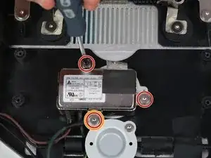
    • El filtro EMI está conectado por tres tornillos. Utiliza el destornillador T10 para quitarlos.

    • El tornillo que sujeta tanto el filtro como un cable que está conectado a él es de un tamaño diferente y debe mantenerse identificable de los otros dos tornillos.

    • El cable verde y amarillo que estaba sujeto por el tornillo diferente está metido detrás de otro componente. Para sacarlo, apriétalo detrás del cable negro y el filtro se podrá quitar de la carcasa.

    Nothing about the power cable itself here. That has to be unplugged first, or when you get to this point, you’ll have to carefully unplug the main power cable from the back of the AC adapter you just removed in Step 13, and feed it through the hole in the back of the case.

    EARL W REYNOLDS JR -

    I was unable to “squeeze” the green/yellow wire behind the black wire because it is adhered to the back case. In order to replace this cable, you’ll need to pry the black cable off the back of the case. Now is a good time to do that so you *can* get the green/yellow wire out.

    R Miller -

Conclusión

Para volver a armar tu dispositivo, sigue estas instrucciones en orden inverso.

Calvin Laverty

Miembro Desde 14/04/15

2126 Reputación

7 comentarios

Power adapter? That's the AC EMI filter, right? My power supply looks like this:

http://www.dvwarehouse.com/661-6048-661-...

The EMI filter will never fail... well, maybe a direct lightning strike.

roger -

That is definitely just a filter. The power supply is the big PCB connected to it. One could say this is an EMI filter along with an IEC input connector...this guide is only useful if you want to replace the connector rather than the actual power supply.

Garrett Mace -

Not sure if the EMI filter will NEVER fail as someone said above. Mine was buzzing and I replaced it and this fixed one of my displays that was buzzing. There are also other causes, including capacitors on the Power Supply board, worn out fan etc.

Charlie Nancarrow -

So are we saying that this is wrong? anyone? I really need to replace my power supply.

Stewart Sensor -

I replace the all in one lightning and charge cable but it has ended up that the lightning cable only works. I thought I connected everything up fine but which connector would stop the charge cable working?

pdspanagel -

Am I imagining things, or was there once a separate power supply guide? I bought the part, and now I can't seem to find that particular guide.. I had the buzzing sound, and now my display won't even turn on-- do I have to replace both, would you think?

Cory Caplan -

Display is going out afther 1 hour of working. I have replace the power supply. But afther installation I still had this problem.

Then I ordered a new Logicboard. and a new cable. Afther installation I still had the same problem !!!. :(

Is it possible that the filter is broken, or the display of the A1407.??

Paul Rovers -