Introducción
Aparte del daño por impacto catastrófico, la razón principal para reemplazar un marco medio en una Switch de Nintendo es porque el riel de montaje del joy-con se ha arrancado brutalmente del marco medio, sin dejar un montaje sólido para un riel de repuesto disponible.
Para restaurar la seguridad de la montura joy-con, es necesario reemplazar todo el marco medio, y esta guía te guiará a través del procedimiento.
Nota: Cuando retires la placa protectora, deberás reemplazar el compuesto térmico entre la placa y el disipador de calor. Dado que la pasta térmica normal no está diseñada para cerrar espacios grandes, el repuesto más parecido es la pasta térmica viscosa K5 Pro. Sin embargo, necesitarás pasta térmica de repuesto normal para la CPU.
-
-
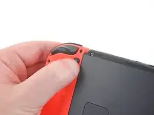
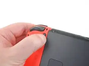
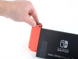
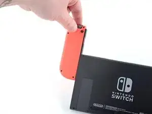
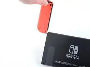
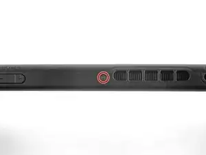
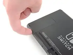
Mantén pulsado el pequeño botón redondo de la parte trasera del mando Joy Con.
-
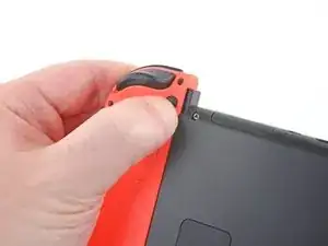
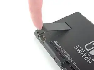
Mientras mantienes pulsado el botón, desliza el mando hacia arriba.
-
-
-
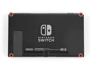
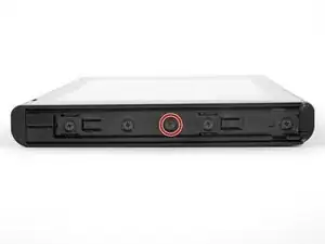
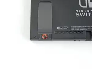
Utiliza un destornillador Y00 para retirar los cuatro tornillos de 6.3mm de longitud que sujetan el panel trasero.
-
-
-
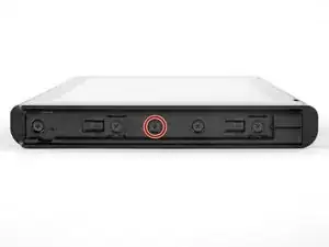
Utiliza un destornillador JIS 000 o un destornillador PH000 oficial de iFixit para retirar los siguientes tornillos que fijan el panel trasero:
-
Un tornillo de 2.5 mm de longitud en el borde superior del aparato.
-
Dos tornillos de 2.5 mm de longitud en el borde inferior del aparato
-
-
-
Usa un destornillador JIS 000 o un destornillador PH 000 oficial de iFixit para retirar los dos tornillos centrales de 3.8 mm situados en los laterales del aparato (uno en cada lado).
-
-
-
Utiliza un destornillador JIS 000 o un destornillador PH 000 oficial de iFixit para retirar el tornillo de 1.6 mm en el pozo de la pata de cabra.
-
Cierra el soporte.
-
-
-
Abre la solapa del cartucho de tarjetas de juego.
-
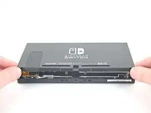
Levanta el panel trasero desde la parte inferior del dispositivo y retíralo.
-
-
-
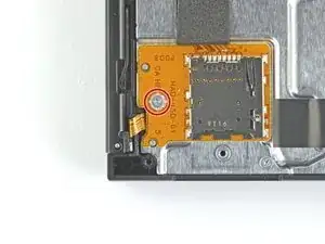
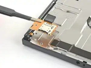
Utiliza un destornillador JIS 000 o un destornillador PH 000 oficial de iFixit para retirar el tornillo de 3.1 mm que fija el lector de tarjetas microSD al dispositivo.
-
-
-
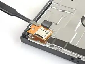
Utiliza tus dedos o unas pinzas para levantar el lector de tarjetas microSD directamente del dispositivo para desconectarlo y retirarlo.
-
-
-
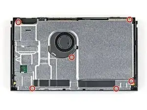
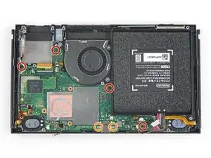
Usa un destornillador JIS 000 o un destornillador PH 000 oficial de iFixit para retirar los seis tornillos de 3 mm que fijan la placa de protección al aparato.
-
-
-
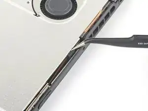
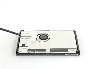
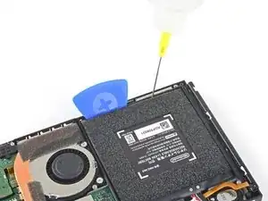
Utiliza tus dedos o unas pinzas para despegar el trozo de espuma que hay en el borde superior del aparato, cerca del puerto de salida del ventilador.
-
-
-
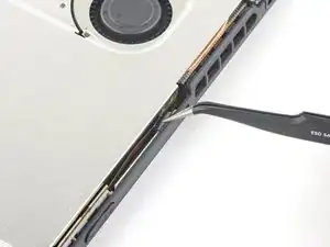
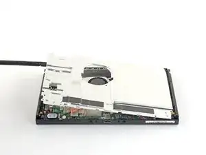
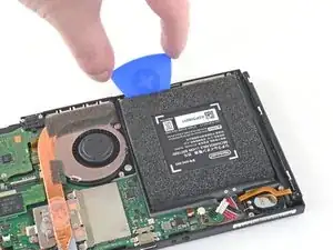
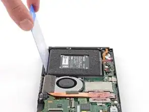
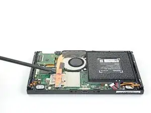
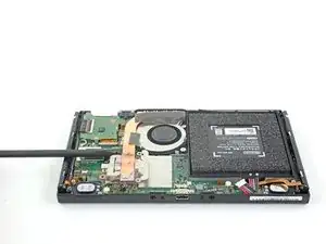
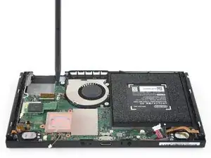
Inserta un spudger debajo de la placa de escudo a lo largo del borde del dispositivo.
-
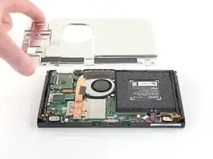
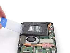
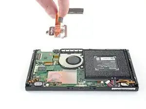
Haz palanca para levantar la placa de escudo y removerla del dispositivo.
-
Puedes reutilizar el compuesto térmico rosa si tienes cuidado. Mantén el compuesto limpio y asegúrate de que haces un contacto sólido entre el disipador de calor y el protector durante el montaje.
-
Si necesitas reemplazarlo, consulta nuestra guía de pasta térmica para quitar el compuesto térmico antiguo y reemplazarlo con un compuesto apropiado, como K5 Pro, durante el reensamblaje.
-
-
-
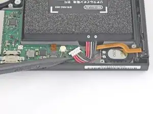
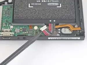
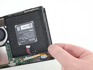
Usa la punta de un spudger para hacer palanca en el conector de la batería hacia arriba y fuera de su zócalo en la placa madre.
-
-
-
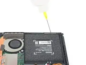
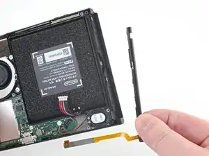
Aplicaunas cuantas gotas de removedor adhesivo ( removedor de adhesivo )concentración (90% o mas alto) de alcohol isopropilico a lo largo del borde superior para debilitar el adhesivo.
-
-
-
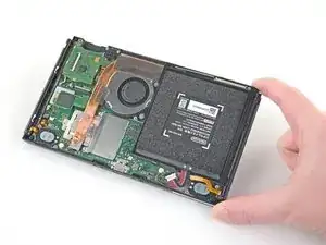
Inclina el borde superior del dispositivo hacia arriba para permitir que el alcohol isopropílico se abra paso por debajo de la batería.
-
Déjalo inclinado durante 1-2 minutos para permitir que el alcohol isopropílico debilite el adhesivo.
-
-
-
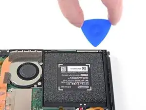
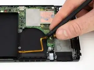
Inserta una púa de apertura en el espacio entre la batería y la pared del compartimento de la batería.
-
Introduce con cuidado la punta de la púa de apertura debajo de la batería y deslízala a lo largo del borde para comenzar a cortar el adhesivo.
-
-
-
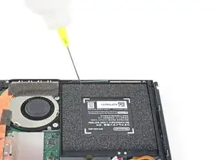
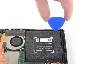
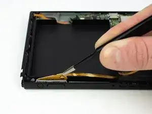
Deja la púa de apertura en su lugar y aplica unas gotas más de removedor adhesivo o alcohol isopropílico dentro del compartimiento de la batería.
-
Inclina el borde superior del dispositivo hacia arriba y espere 1-2 minutos hasta que el alcohol isopropílico debilite el adhesivo.
-
-
-
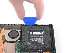
Continúa deslizando la púa de apertura más profundamente a lo largo del borde superior de la batería, cortando más adhesivo debajo.
-
-
-
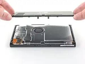
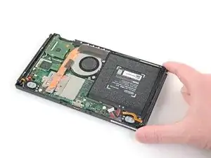
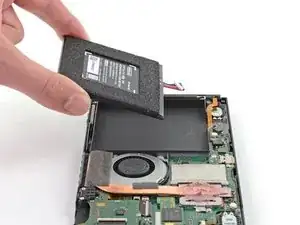
Una vez que haya suficiente espacio, inserta una tarjeta de plastico debajo de la batería y levante lentamente la batería.
-
Remueve la batería
-
-
-
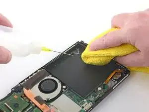
Utiliza un removedor de adhesivo o alcohol isopropílico y un paño de microfibra para limpiar cualquier resto de adhesivo que haya quedado en la batería antes de instalar la nueva batería.
-
-
-
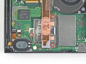
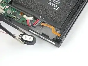
Usa un destornillador JIS 000 o un PH 000 oficial de iFixit para remover tres tornillos de 3 mm asegurando el disipador a la placa madre
-
-
-
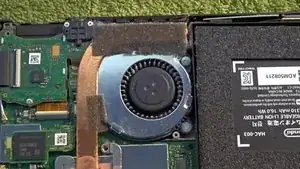
Despega con cuidado las dos piezas de espuma pegadas sobre el disipador y el ventilador.
-
Introduce la punta de un spudger debajo de la parte de la espuma que no está pegada a nada,
-
Presiona la parte superior de la espuma con el dedo para mantenerla en su sitio.
-
Pasa la punta del spudger por debajo de la espuma hasta el otro extremo de la espuma para liberarla.
-
-
-
Usa una spudger o tus dedos para levantar el disipador arriba y fuera de la placa madre para removerlo
-
Aplica pasta térmica a todas las superficies a las que se les haya aplicado pasta térmica anteriormente. Esto incluye entre el tubo de calor y el escudo de aluminio, que el Switch usa como disipador de calor adicional.
-
-
-
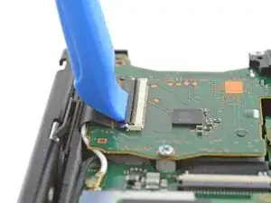
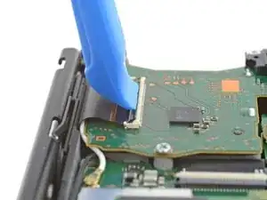
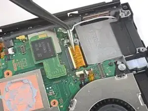
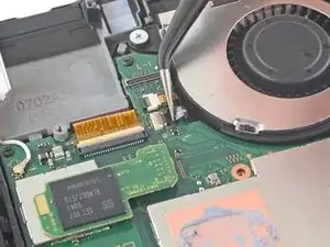
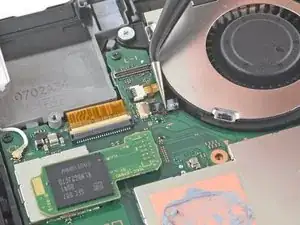
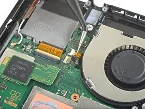
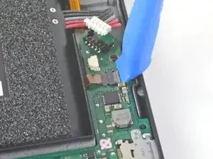
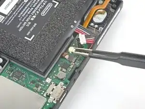
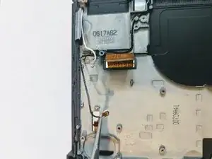
Usa una herramienta de apertura o tu uña para levantar el candado del conector ZIF del digitalizador
-
-
-
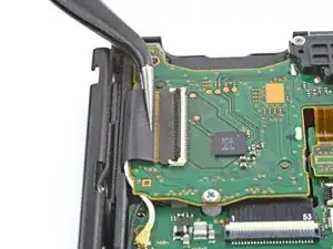
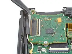
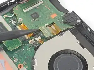
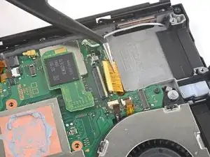
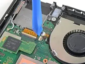
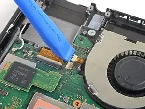
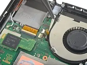
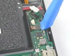
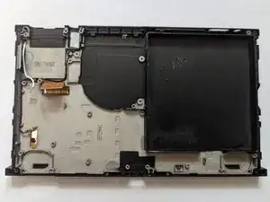
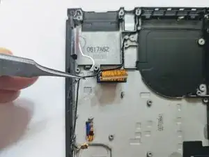
Utiliza unas pinzas para deslizar suavemente y de forma horizontal el cable plano del lector de tarjetas de juego fuera de su conector.
-
-
-
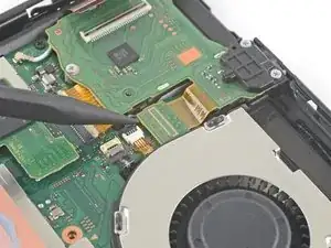
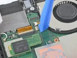
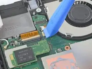
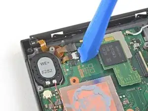
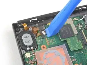
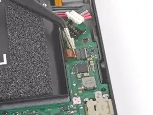
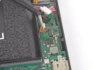
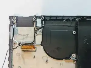
Usa la punta de un spudger para levantar el conector del jack de audífonos y el lector de tarjetas de juego y desconectarlo de la tarjeta madre
-
-
-
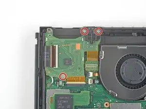
Usa un destornillador JIS 000 o un PH 00 oficial de iFixit para remover los tres tornillos de 3.1 mm asegurando el conector de audífonos y el lector de tarjetas de juegos del dispositivo
-
-
-
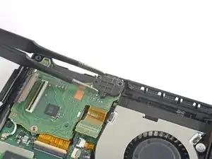
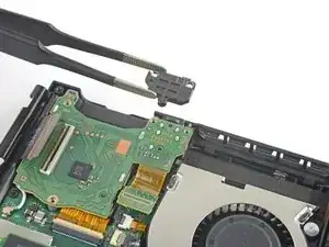
Usa un par de pinzas o tus dedos para remover la tarjeta del conector de audífonos y el lector de tarjetas de juego.
-
-
-
Usa una herramienta de apertura, spudger, o tu uña para levantar una pequeña, solapa de seguro en el conector ZIF del cable plano del LCD
-
-
-
Usa una herramienta de apertura, spudger, o tu uña para levantar una pequeña, solapa de bloqueo en el conector ZIF del cable del ventilador.
-
-
-
Usa un par de pinzas para jalar el cable del ventilador afuera de su conector en la placa madre.
-
-
-
Usa una herramienta de apertura, spudger, o tu uña para levantar una pequeña solapa de bloqueo en el conector ZIF del cable plano de los botones de volumen y encendido.
-
-
-
Usa una herramienta de apertura, spudger, o tu uña para levantar una pequeña solapa de bloqueo en el conector ZIF mas pequeño del cable plano del LCD.
-
-
-
Usa la punta de un spudger, una herramienta de apertura, o tu uña para levantar la pequeña solapa de bloqueo del conector ZIF del cable de datos del riel del sensor Joy Con.
-
-
-
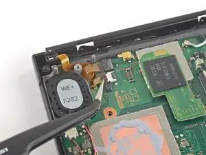
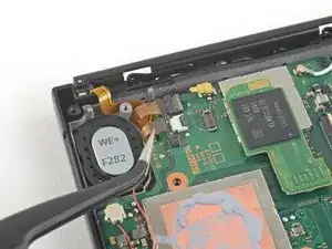
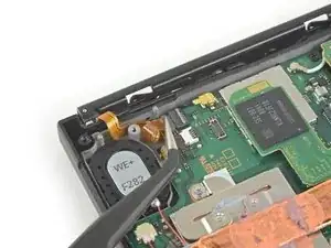
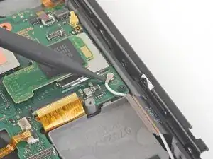
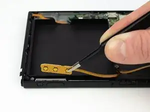
Usa la punta de un spudger para levantar el cable de la antena negra arriba del zocalo en la placa madre.
-
-
-
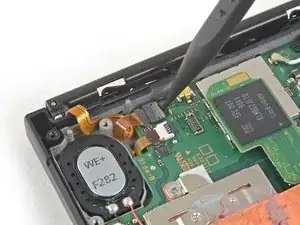
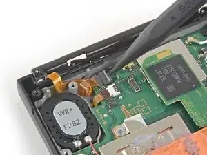
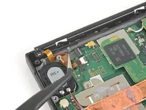
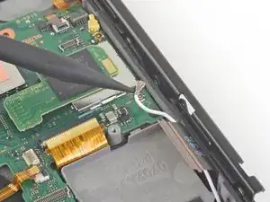
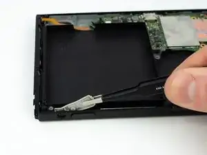
Usa la punta de un spudger para levantar el cable de la antena blanca arriba del zocalo en la placa madre.
-
-
-
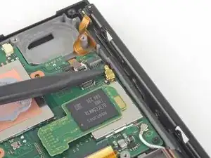
Usa tus dedos o un par de pinzas para jalar el conector de la bocina derecha afuera del zocalo en la placa madre.
-
-
-
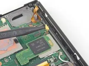
Usa tus dedos o un par de pinzas para jalar el conector de la bocina izquierda afuera del conector de la placa madre.
-
-
-
Usa una herramienta de apertura, spudger, o tu uña para levantar una pequeña solapa de bloqueo en el conector ZIF del cable de datos del riel del sensor Joy Con.
-
-
-
Usa un par de pinzas para deslizar el cable del riel de datos Joy Con afuera de su conector en la placa madre.
-
-
-
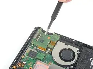
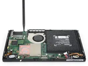
Usa un destornillador JIS 000 o una herramienta oficial iFixit PH000 para retirar los siguientes tornillos:
-
Cuatro tornillos de 2.5 mm
-
Dos tornillos de 3.1 mm
-
-
-
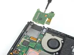
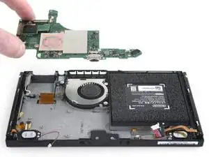
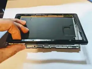
Inserta una spudger entre el espacio de la placa madre y el marco.
-
Cuidadosamente levanta la placa madre y remuevela del marco.
-
-
-
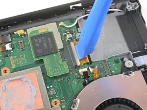
Si sólo vas a sustituir el altavoz izquierdo, sáltate los dos pasos siguientes.
-
Utiliza tus dedos o unas pinzas para sacar el conector del altavoz directamente de su hueco en la placa base.
-
-
-
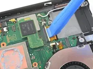
Utiliza la punta de un spudger para levantar el altavoz.
-
Usa tus dedos o unas pinzas para retirar el altavoz derecho.
-
-
-
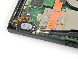
Usa tus dedos o unas pinzas para retirar el conector del altavoz directamente de su conector en la placa base.
-
-
-
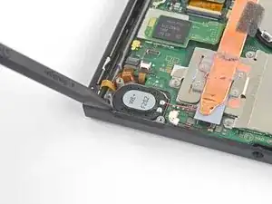
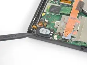
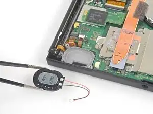
Utiliza la punta de un punzón para hacer palanca en el altavoz y soltarlo del hueco del altavoz.
-
-
-
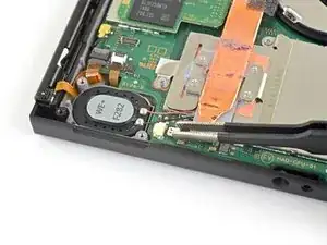
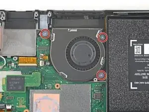
Usa un destornillador JIS 000 o uno PH 000 IFixit para extraer los tres tornillos (4,8mm) que sujetan el ventilador.
-
-
-
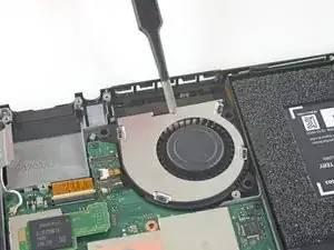
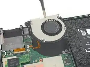
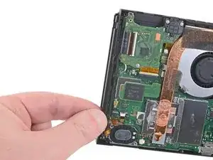
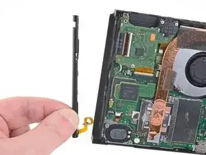
Usa unas pinzas o con los dedos para extraer el ventilador hacia arriba y sacarlo del interior de la consola.
-
-
-
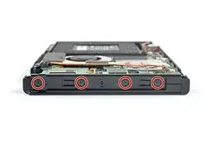
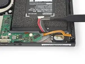
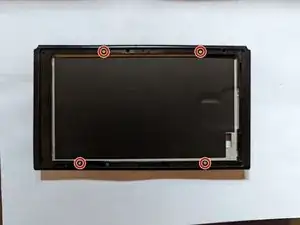
Usa un destornillador JIS 000 o uno PH 000 IFixit para retirar los cuatro tornillos (3,7mm) que sujetan el carril al marco del dispositivo.
-
-
-
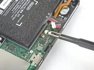
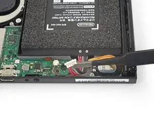
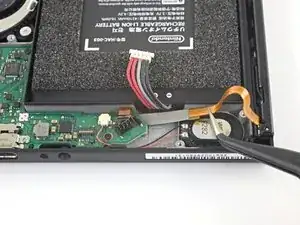
Usa unas pinzas o los dedos para desconectar el cable de la batería sin dañar el cable del carril del Joy Con.
-
-
-
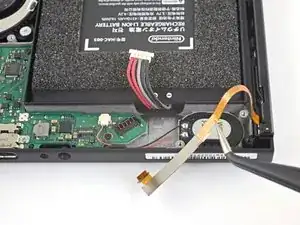
Usa unas pinzas o los dedos para desconectar el cable de la batería sin dañar el cable del carril del Joy Con derecho.
-
-
-
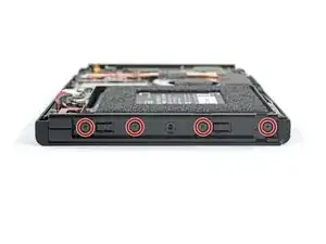
Usa un destornillador JIS 000 o uno PH 000 IFixit para retirar los cuatro tornillos (3,7mm) que sujetan el carril al marco del dispositivo.
-
-
-
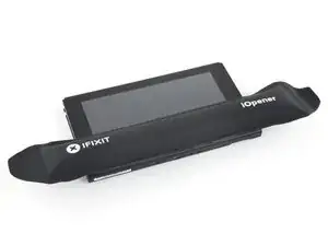
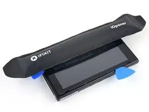
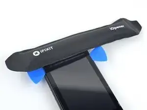
Calienta con iOpener y aplícalo al borde inferior de la pantalla alrededor de dos minutos para debilitar el adhesivo.
-
-
-
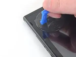
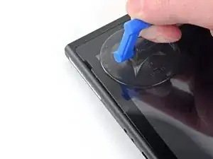
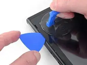
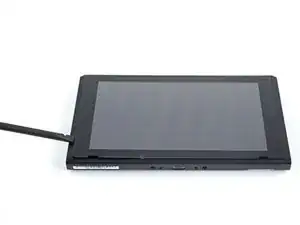
Coloca una ventosa en la esquina inferior izquierda de la pantalla.
-
Estira con fuerza hacia arriba, si haces fuerza lentamente podría provocar una fisura.
-
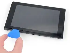
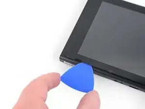
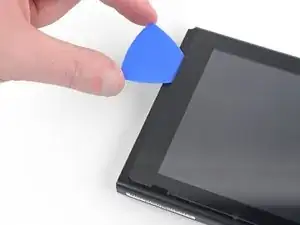
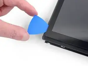
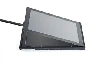
Introduce el borde de una púa de plástico en la separación, asegurándote que sólo sean 5mm.
-
-
-
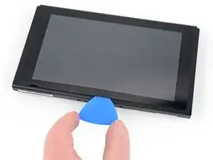
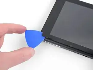
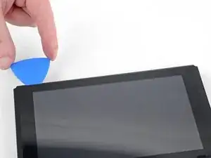
Desliza la púa a lo largo del borde inferior para despegar el adhesivo.
-
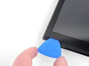
Deja la púa introducida entre las dos piezas para evitar que vuelva a pegarse el adhesivo.
-
-
-
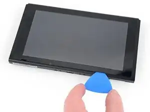
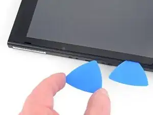
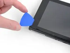
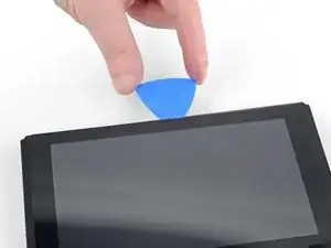
Inserta una segunda púa en la separación a la izquierda de la primera.
-
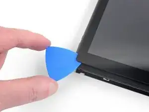
Desliza la segunda púa hacia la izquierda.
-
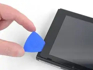
Deja la púa insertada entre las dos piezas.
-
-
-
Calienta el borde izquierdo de la pantalla alrededor de dos minutos para reblandecer el adhesivo.
-
-
-
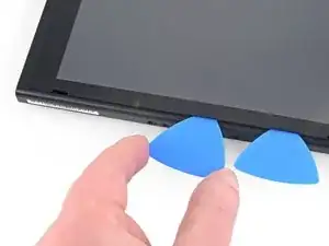
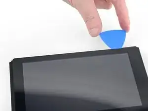
Continúa deslizando la púa alrededor de la esquina inferior izquierda para despegar al adhesivo.
-
-
-
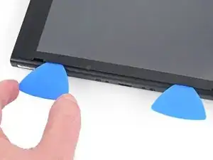
Continúa deslizando la púa a lo largo del borde izquierdo de la pantalla para despegar el adhesivo.
-
-
-
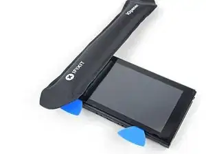
Calienta el borde superior de la pantalla alrededor de dos minutos para ablandar el adhesivo.
-
-
-
Continúa deslizando la púa alrededor del borde superior de la pantalla para despegar el adhesivo.
-
-
-
Continúa deslizando la púa a lo largo del borde superior de la pantalla para despegar el adhesivo.
-
-
-
Calienta el borde derecho de la pantalla alrededor de dos minutos para ablandar el adhesivo.
-
Coloca el lado plano de un puntero en la separación a lo largo del borde izquierdo de la pantalla.
-
Muy suavemente deslízalo despacio por el borde izquierdo de la pantalla, separándola como si abrieras un libro.
-
-
-
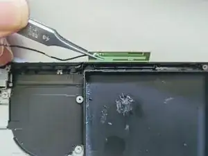
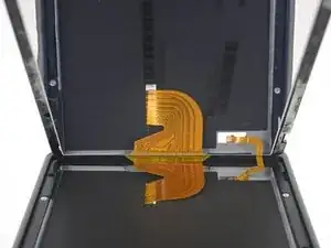
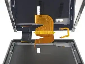
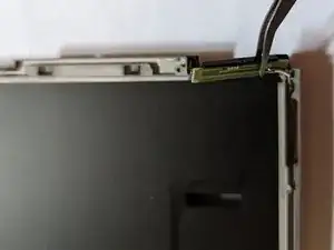
Despega el borde derecho de la pantalla separándolo del dispositivo, retirando los cables flexibles a través del marco.
-
-
-
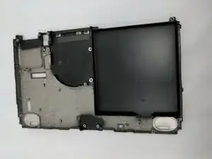
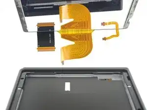
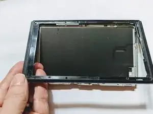
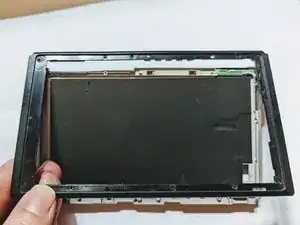
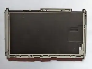
Despega el borde frontal del marco y entonces desliza el marco hacia arriba separándolo de la pantalla.
-
-
-
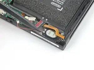
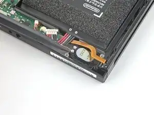
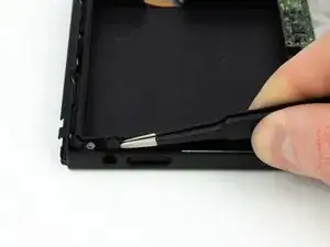
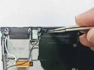
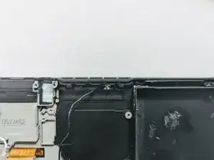
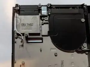
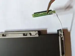
Comprueba que el cable coaxial no está doblado o atascado en las guías internas que lo sujetan.
-
-
-
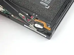
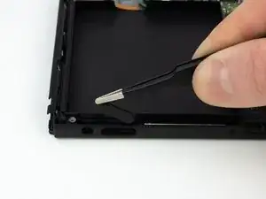
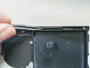
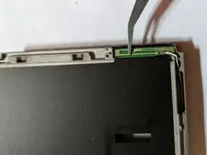
La antena está sujeta con un adhesivo ligero, simplemente debes levantar suavemente para extraerla.
-


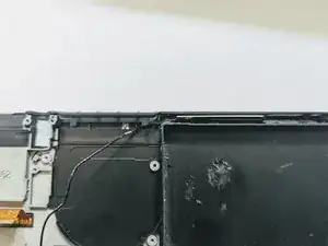
Para volver a armar tu dispositivo, sigue estas instrucciones en orden inverso.

5 comentarios
Great guide will be attempting this soon so this guide has given me some hope! I can’t seem to find the black insulation layer on the last step would that be a generic insulating foam or something else?
Thanks, it should work, as I actually followed my own instructions the entire way through the replacement, although I had to add three other guides for completeness; the two antenna guides and the front frame guide.
I’m afraid I sidestepped the issue of the black insulation; I opted to buy a used frame that clearly showed the insulation still in place once I realized all of the new ones came without it. If you do come up with a solution for a replacement, we’d love to hear about it; I personally can’t think of a suitable substitute offhand.
Oh, one note on this guide; it’s put together using existing guides for the individual part removals, and as such it duplicates the instructions for removing some of the connectors such as the speakers and the display. So don’t worry if the instructions tell you to unplug a connector you’ve already unplugged; that’s just an artifact of combining separate guides. For example, both the motherboard and LCD replacement instructions tell you to unplug the LCD and digitizer cables
Jerry W -
Thanks for the reply,
I was planning on doing this repair as a switch I have purchased has cracked plastic at the bottom of the casing where the fan vents are but I’m weighing up the pros and cons of stripping it down purely for that reason.
I can’t find a housing with that thermal pad anywhere which puts me off buying the ones that claim to be OEM if they don’t come with it by default.
I found some closed cell Polyethylene insulating foam sheets that are about 2mm thick so I’m assuming that’s similar on eBay so might give that a try and see how it compares to the original.
I poked around but had no luck finding anywhere the pad is sold separately; however I did come across a midframe being sold on Amazon with the pad (OEM pulls, removed from Switches). I’ve included a link in the parts list. The really good news is, it’s only about $11 US! Dang, wish I’d seen this when I was doing my replacement!
Jerry W -
Hey Cameron, just re-reading your latest comment and I have to wonder if you really need to do a full midframe replacement. If its just cracked plastic, that should mean just doing a front frame replacement instead of a full midframe. Still a lot to do; the main differences are that you don't have to remove the battery and speakers which would be good as the battery is pretty hard to pull.
Jerry W -