Introducción
Mi MX Vertical desarrolló un doble clic fantasma en el botón izquierdo del mouse después de aproximadamente un año de uso. Sin garantía ni paciencia, lo desarmé para ver si podía reemplazar los interruptores. Para mi sorpresa, ¡desarmar y reparar el mouse fue casi un sueño!
El mouse se envió con interruptores OMRON D2FC-F-7N (10M) instalados. Puedes encontrar repuestos en muchos minoristas online, pero yo opté por reemplazarlos con interruptores OMRON D2FC-F-K (50M) en su lugar. Probablemente puedas elegir un tipo diferente de interruptor si lo deseas, siempre que comparta el factor de forma del D2F. ¡Este es un ejercicio que le dejo al lector!
Esta guía requiere soldadura, pero afortunadamente es un orificio pasante en algunas partes relativamente grandes. La parte más difícil del trabajo es mantener firme la placa mientras se suelda el primer contacto de los interruptores.
Partes
-
-
Apaga el mouse antes de comenzar el desmontaje.
-
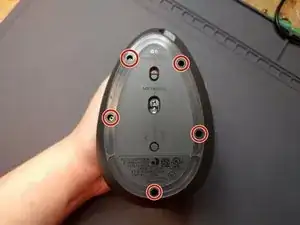
Dale la vuelta al mouse para que el sensor y el interruptor de encendido queden frente a ti.
-
Inserta un spudger de plástico entre cada pie deslizante y la base de plástico del mouse. Haz palanca en el deslizador adhesivo de la base para acceder a los huecos de los tornillos.
-
-
-
Retira los cinco tornillos Phillips de la parte inferior del mouse.
-
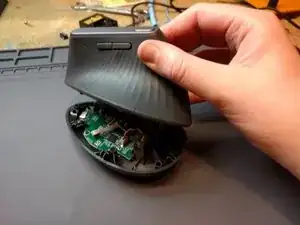
Dale la vuelta al mouse, sosteniendo tanto la base como la parte superior para evitar que se desmonte.
-
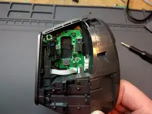
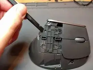
Levanta la parte superior del mouse hacia arriba y hacia afuera de la base. Una vez que esté libre de los orificios de los tornillos, gira la parte superior para colocarla sobre el lado del botón principal.
-
-
-
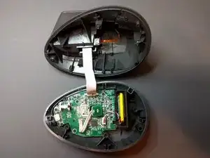
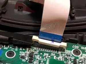
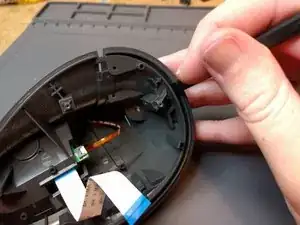
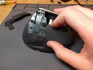
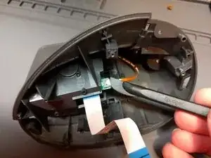
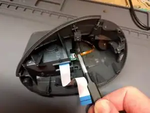
Usa un spudger de plástico para levantar ambos lados del bloqueo del cable plano en la base del mouse.
-
Levanta el cable plano para sacarlo de su zócalo en la base.
-
-
-
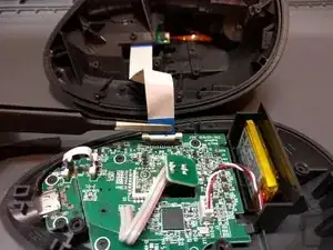
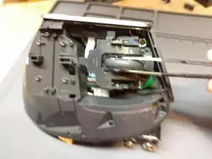
Voltea la parte superior del mouse para ver su interior.
-
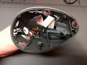
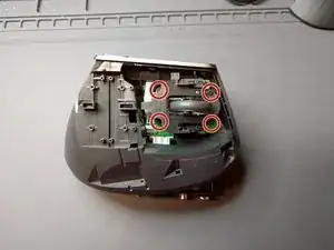
Retira los cinco tornillos Philips que sujetan la parte superior sujetando la carcasa por arriba. No es necesario quitar el tornillo más cercano al botón de cambio de DPI ubicado en la parte superior del mouse.
-
-
-
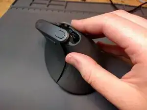
Voltea la parte superior del mouse para que esté en la orientación que tendría durante el uso normal. Gira la parte superior del mouse para que los botones principales y la rueda queden frente a ti.
-
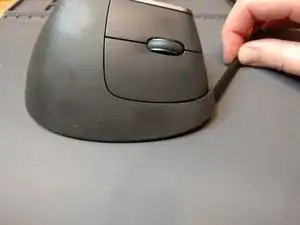
Inserta un spudger de plástico en la costura de la parte delantera del mouse, más cerca del lado derecho de los botones. Debería salirse de su lugar.
-
Aplica presión al borde inferior de la cara debajo del medio de los botones del mouse. Debería salirse más de su lugar.
-
Voltea la parte superior del mouse para que los botones principales y la rueda del mouse queden hacia la superficie de trabajo.
-
Inserta un spudger de plástico en la costura entre la cara adherente y la base de plástico del mouse en su lado derecho. La cara debería salirse casi por completo de su lugar.
-
-
-
Voltea la parte superior del mouse para que esté en la orientación que tendría durante el funcionamiento normal. Gíralo para que los botones principales y la rueda queden de espaldas a ti.
-
Coge la cara adherente cerca del botón del conmutador DPI y muévela hacia la izquierda y hacia la derecha mientras la alejas de la parte superior del mouse.
-
-
-
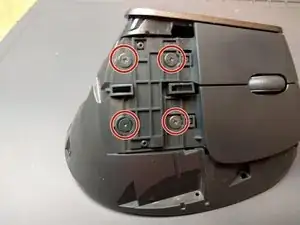
Gira la parte superior del mouse para que los botones principales y la rueda queden frente a ti.
-
Retira los cuatro tornillos Phillips anchos que sujetan los botones del mouse al chasis superior.
-
Inserta un spudger de plástico entre el lado izquierdo del botón izquierdo del mouse y el chasis. Haz palanca suavemente en el botón para liberarlo. Debe saltar, pero puede requerir un ligero empujón hacia la derecha para separarse por completo.
-
Coge el botón derecho del ratón a la izquierda de la rueda del ratón. Sácalo hacia la izquierda, alejándolo del chasis.
-
-
-
Retira los cuatro tornillos Phillips que sujetan el ensamblaje de la rueda del mouse al chasis superior.
-
Toma el ensamblaje del mouse por la rueda o el plástico y sácalo del chasis.
-
-
-
Usa un spudger de plástico para girar el bloqueo en el conector del cable plano para el botón del conmutador DPI.
-
Saca el cable plano de su conector.
-
-
-
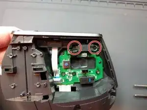
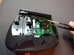
Retira los dos tornillos Phillips que sujetan la placa del micro-interruptor de clic izquierdo al chasis superior.
-
Tira suavemente hacia afuera y gira la placa para que quede libre del chasis.
-
-
-
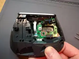
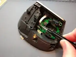
Usa un spudger de plástico para girar el bloqueo en el conector del cable plano para el ensamblaje del botón de navegación, luego levanta el cable plano para sacarlo del conector.
-
-
-
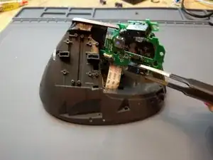
Toma la placa base del chasis superior con el micro-interruptor de clic derecho. Sácalo hacia ti para liberarlo de sus clavijas en el chasis, luego levántalo directamente hacia arriba y hacia afuera del chasis superior.
-
-
-
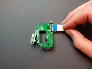
Usa un spudger de plástico para girar el bloqueo en el conector del cable plano, luego retira el cable plano del conector.
-
-
-
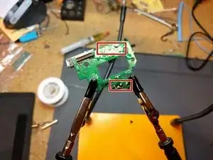
Agrega un poco de soldadura nueva a cada uno de los tres terminales en un micro-interruptor.
-
Mientras retiras el micro-interruptor de la placa, calienta sus tres terminales. El interruptor debe quedar libre.
-
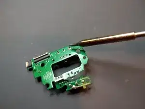
Limpia los terminales de cualquier exceso de soldadura usando una ventosa de soldadura y una trenza de soldadura. Los agujeros en el tablero deben ser claramente visibles, debe ser fácil insertar sus nuevos interruptores.
-
Repite estos pasos para el otro micro-interruptor.
-
-
-
Inserta los contactos del interruptor a través de los agujeros de la placa.
-
Suelda un contacto del interruptor a la placa mientras presionas el interruptor en la placa. Deja que el interruptor se enfríe.
-
Suelda los contactos restantes a la placa, permitiendo que el interruptor se enfríe cada vez.
-
Para volver a armar tu dispositivo, sigue los pasos 1 a 14 en orden inverso.
26 comentarios
Thanks! This is perfect.
Super guide with details, done step by step, picture by picture, my MX Vertical working great now :) THANK YOU !!!!!
Thanks for this guide !!!
Regarding Logitech quality: it’s a shame that such an expensive mouse (paid 100€ !) has only “normal” micro switches (10M)
I’ve also replaced the switches by a 50M variant (OMRON D2FC-F-7N(50M))
Woah 100 bucks sounds like a theft. I had it for 35€ on Amazon on nov 2019.
More details about step 1 can be found here : Reemplazo de las patas del Logitech MX Vertical
Guillaume Felix -