Introducción

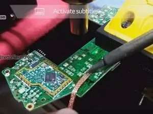
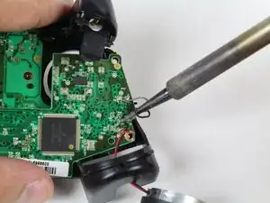
Técnica de desoldar con [malla gootwitck], estación de aire caliente y soldador yihua. (el aire caliente a 100 °C ayuda a precalentar la placa lógica de control).

  1. nCPWIVIPPnPioQek
    • Retira la cubierta del paquete de baterías.

    • Retira las baterías.

  2. BCoOrGwESawovJpX
    BCoOrGwESawovJpX
    CYTch3arFkuHOaol
    • Recomendamos el uso de un spudger de nylon para este paso. Se muestra un spudger de metal.

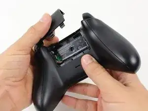
    • Sujeta el controlador firmemente para quitar las asas laterales, encajando un spudger en la costura entre la parte delantera y las placas del mango.

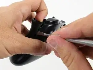
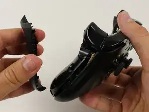
    • Levanta la placa lateral alejándola de la placa frontal moviendo el spudger hacia adelante y hacia atrás. Tendrás que hacer esto en toda la costura de la placa lateral.

    Start prying the side plate off underneath the trigger, this makes it easier to disconnect the other clips connecting the side plate to the backplate.

    Brandon -

    One you take it off, is it possible to click it back in?

    Aiden Bear -

    As long as you don’t exceed the couple tons you need to take it off you should be able to put it back.

    Brandon -

    I don’t have a squdger

    TimidFerret4982 Gaming -

    getting those handles back on seems impossible, they just dont fit as well, a gap remains even after snapping into place.

    Dont think ill be doing this in the future

    Spoutin Wyze -

    edit: wiggled the bo9ttom middlewith the handles off and somethign finally “clicked” into place for that extra 1/4 mm for the down arrow on my D-Pad to click back up into place!.

    Spoutin Wyze -

  3. NIQhMF4yRuvR3EOl
    NIQhMF4yRuvR3EOl
    JPprWqFDRTUcXoCS
    • Hay un tornillo escondido en la parte central trasera del mando

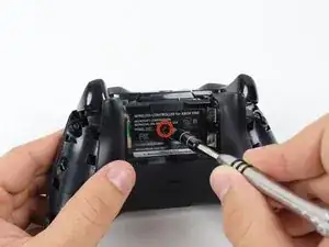
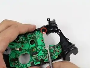
    • Utiliza el destornillador para hacer un agujero en el centro, y poder así, quitar el tornillo

    • También puedes quitar la etiqueta si no deseas hacer un agujero en ella

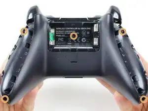
    • Quita los 5 tornillos de 10mm que están en la parte trasera del mando utilizando el "T8 Security Torx Screwdriver"

    i damaged my screws. how do i get the screws out?

    tenzin -

    wait. i just watched a video guide on ifixit's youtube channel about damaged screws. i'll try those methods.

    tenzin -

    It's a t8 or t9 security bit btw, I got the top two out with a regular T8, but the bottom two and middle needed a T9 Security bit.

    David Loper -

    All five faceplate/backplate screws in the controller I disassembled were T8 security fasteners.

    John Dziedzic -

    Am I doing something wrong because I got the tool it said I needed and got the middle screw out but the others have a bump or something in the center of the screw and it won't fit.

    kolton77 -

    The T8 is only good for the middle screw on my One S controller. The others require something bigger

    Matej Skelo -

    These requires SECURITY Torx bits (they have a cannulated hole in the driver). I don't believe the iFixIt branded driver is cannulated but you can buy a set of bits from DeWalt DWAX200 which is overkill but has what you need.

    jhighsmith -

    The driver that iFixIt sells is cannulated.

    jhighsmith -

    where do you get this dumb ass screw driver

    Jake Zweier -

    iFixit Store #IF145-027-3

    VauWeh -

    You can bypass it with a 1.5mm flathead.

    Marianne Sandling -

    thank you for this. worked for me

    Mr Anderson (Evolluisionist) -

    These screws required a T10, not T8.

    Armand -

    TR9. A $10 kit from Walmart has the bit/driver in it and extra goodies to make life simple.

    Matt Martin -

    As weird as it sounds, the top 2 came out for me with a flathead- but the bottom two and the middle one wont

    macybrooksevans -

    If you damage the middle part of the screws you can still take it out with the same screwdriver.

    Kev God -

    Thank-You :)

    Isaiah -

    needed a T8H, not easy to see.

    on a grey green xbox one controller

    Michael -

    You need a T8 and the kit is not $10 it’s $13.88 Hyper Tough Electronic Kit. In the hardware section at WalMart it a T8 because I tried everything and only a T8 fit it like a magnet. And the dumbass that wrote the article there is only 1 freaking screw.

    Bear Darazs -

  4. CN1rEMvQC3myRLyq
    • Retira la placa posterior.

  5. hWBUR3YZiAAiU3As
    • Retire la placa frontal.

  6. NF1M5HTNtuRwQV66
    NF1M5HTNtuRwQV66
    YPrTGnbbQiLpdCcS
    • Podras dejar los motores vibradores colgando fuera de su base

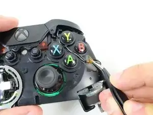
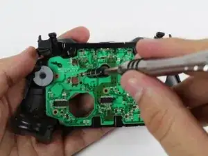
    • Desolda los cables rojos y negros de la parte superior de la placa

    • Desolda los cables negros y grises de la parte superior de la placa

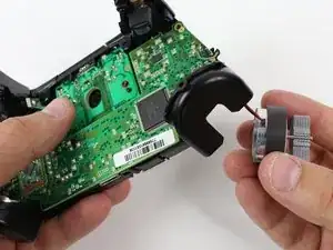
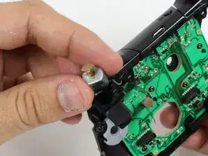
    • Remueve los motores vibradores y déjalos aun lado.

    • Se cuidadoso cuando usas el cautín, no dañes otros componentes o te lastimes.

    • Para mayor información de como soldar, presiona aquí

    Steps 6-8 aren't completely necessary, and are very risky if you aren't good at soldering. It would seem the only reason to remove the motherboard and mess with all this soldering is just so you can reach both screws on the trigger in step 10. However, you can reach them already with a small-bodied screwdriver. Although you might have to rest the screwdriver on the black square processor to reach the bottom screw, it shouldn't damage the processor or motherboard to jimmy that screw out.

    Robert Rapier -

    like mentioned by ‘Robert Rapier’ you can skip the de-soldering in most cases,

    for example cleaning or changing the buttons is doable, but the grey and black wires are pretty short

    and wired through the inner case so it can get a bit fiddly and you have to be careful not to damage them in the process.

    If you have a soldering station around i would still recommend using it.

    yKekS Yzz -

  7. BY2UC6W4D1LECNDH
    • Desatornilla los dos tornillos de T6 de 7mm localizados cerca de las bases de los motores.

    Are these just T6 screws or Torx security T6 that is cannulated?

    Kenan Vickstrom -

    The outer screws are security screws. The ones on the system boards are Torx.

    Rongwey -

  8. haVbje2oHVch2uMH
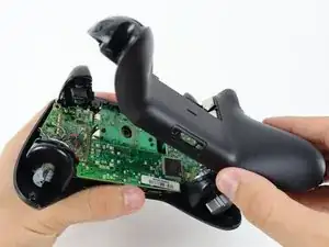
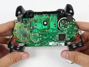
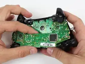
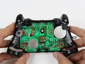
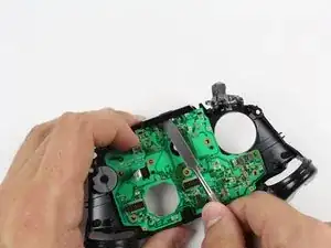
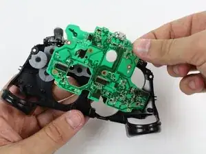
    • Sujeta firmemente la placa superior cerca del medio

    • Levanta hacia arriba mientras mueve ligeramente la placa base hacia adelante y hacia atrás.

    • Levantar la placa base requerirá algo de fuerza.

  9. jmvGURsBm2dTB1RM
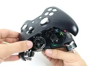
    • Quita la cinta amarilla que mantiene los cables en su posición en la parte delantera del controlador.

  10. 16i4vRk5ocpOkyRF
    16i4vRk5ocpOkyRF
    jHXPStWO4qmWAdWL
    DWF3KMdZQFpiOH2I
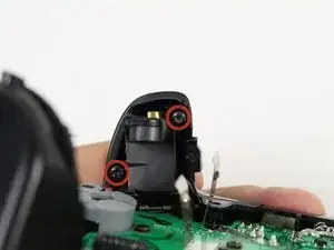
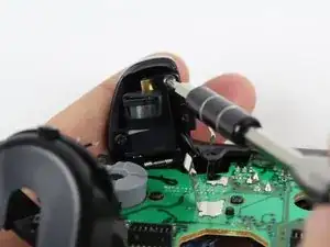
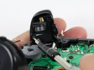
    • Desatornilla los dos tornillos T6 Hex de 7 mm alojados en la parte de la abajo de los disparadores.

  11. MVBJPXd2ZlbJKyNL
    • Quita las cubiertas de los disparadores.

  12. KRfuQorOMEtbhUQC
    • Desuelda los cables que van a la placa base.

    • Quita los motores de vibracion desde sus enchufes y tira del cable con ellos

    Perso après le remontage ça n'a jamais refonctionné ma manette détecte plus du tout les gachettes et jai changé les joysticks en même temps et eux non plus ne detecte plus….

    Tuto Free -

  13. UsaBcmkMJRAaUqC4
    UsaBcmkMJRAaUqC4
    M4H2r4164KJvDEMY
    • Retire los seis tornillos T6 Torx ubicados en la placa base inferior.

    Where can I find the connectors at for the motherboard??

    lillarrypimp1993 -

    This guide completely skips the part about removing the trigger buttons. There are 2 screws per trigger that need to be removed so there are actually 10 T6 screws to remove.

    Navy Vet 2015 -

    There’s also 2 small rumble packs under the trigger buttons that no one mentioned. Someone got lazy when writing this step.

    Navy Vet 2015 -

    Hey @jasonasnes good catch! It looks like maybe they forgot to add the trigger/trigger rumble motor prerequisite, so I went ahead and added that in there. That guide makes no mention of how the rumble motors are attached, but I think they’re soldered to the motherboard, so I added a note to desolder those wires prior to removal. I think you could probably also just desolder those wires and leave the triggers in place when removing the motherboard, but I’m not certain! Hope that helps!

    Sam Goldheart -

    @sam I was able to complete this with the missing information but thank you for updating it for those to come in the future. Minus these couple of discrepancies and it’s a great guide. Yes, all 4 of the rumble motors are soldered onto the upper motherboard. Step 6 actually highlights this with the exception of mentioning the 2 small rumble motors in the triggers. You bring up a good point, it might be possible to leave the triggers in place during this process. I used this guide as a teardown instead of as a replacement so I could refurbish the plastic shell and clean the interior of my day one controller so I completely stripped mine. However, I believe that the triggers could remain in place if your goal is to get to the lower motherboard.

    Navy Vet 2015 -

    You can lift off the top motherboard without desoldering the black/red wires to the large rumble motors, just be careful because the wires are delicate enough that you can break them off at the solder joint. It’s not a huge deal if you do, because they’re long enough that you can strip the ends and have plenty of room to resolder.

    You can even very carefully remove the lower motherboard without desoldering the black/gray wires, and without removing the trigger assemblies, but there’s almost no room to work in there if you choose to go this route, because the wires will leave you only at most an inch of space to get in there under the lower motherboard. Also, leaving the trigger assemblies in place makes it very difficult to get the lower motherboard back into place without pinching or moving the conductive rubber button pad.

    Talia Margherita -

  14. Y4ScikhYpe6alShJ
    Y4ScikhYpe6alShJ
    ePMCPHLVsAahjODF
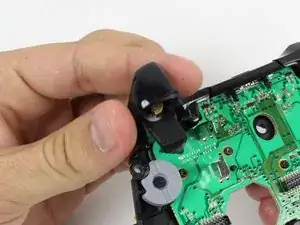
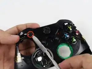
    • Quite los parachoques sacándolos de las clavijas que los aseguran, usando un spudger. Están ubicados en la parte frontal y posterior del controlador.

    • Se recomienda un spudger de nylon estándar para este paso. Usar un spudger de metal cerca de la placa base como se muestra arriesga dañar su dispositivo.

    At some point I had 2 little white pieces come out and I didnt see them till the very end. Does anyone know where these are spossed to go? They kinda look looe shims? Thank you.

    myles bartlett -

    They go behind the trigger buttons on the board against the metal. Narrow side towards the button.

    Rongwey -

  15. XgGEjIXarQBOhD2s
    XgGEjIXarQBOhD2s
    juf5yTFyN3TaCeIn
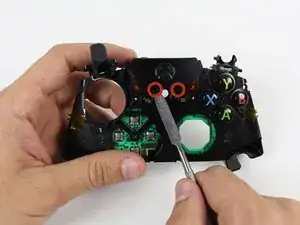
    • Levante la pieza que rodea el botón Inicio de sus clavijas.

    • Sacarlo del otro lado, usando un spudger en los pasadores.

    • Se recomienda un spudger de nylon estándar para este paso. Usar un spudger de metal cerca de la placa base como se muestra arriesga dañar su dispositivo.

    • Eliminar esta pieza puede requerir mucha fuerza.

    2 things missing in this step:

    1) You will have to press down on the power button in order to release the plastic retaining piece.

    2) The button that syncs the controller to the system completely separates from the plastic frame. If you're not careful you could lose the thing.

    Navy Vet 2015 -

    Thanks NavyVet2015!

    The sync button fell out on me and I was pondering what it was for a while.

    Nothing is holding that little guy in so watch it!

    CrazedCanuck18 -

    カバーを戻す前にsyncボタンを本体側に付けてから被せた方が良い

    xbox_user -

  16. YPAmqNqOVVuSGQQT
    • Retire la placa base inferior.

    That’s the TOP motherboard.

    Ken D. -

Conclusión

Para volver a armar tu dispositivo, sigue estas instrucciones en orden inverso.

@HectorNavarroMX

Miembro Desde 26/06/18

3653 Reputación

4 comentarios

Do you know where we can get the original analogue module for the joystick?

Farhan Feroze -

it does not exists, so you should buy generic replacement spare part

@HectorNavarroMX -

I love welding technics. This post has clear ideas on how to replace the joystick and shows in detail that’s I like it. I also try to fix many things, and it’s delightful. Thanks for sharing your ideas.

Anthony -

I just created welding related blog and you will find here more: bestmigwelders.org

Anthony -